any ideea? what do you think abaut this? can someone give me the values?
http://users.swing.be/edwinpaij/images/shortcircuitprotection1.gif
http://users.swing.be/edwinpaij/images/shortcircuitprotection1.gif
An externally hosted image should be here but it was not working when we last tested it.

copilu said:any ideea? what do you think abaut this? can someone give me the values?
http://users.swing.be/edwinpaij/images/shortcircuitprotection1.gifAn externally hosted image should be here but it was not working when we last tested it.
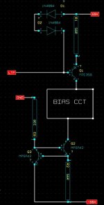
R1/2/3/4/5 1K at a guess.
Re 0R22 10 watt depending on amp ouput power.
I would also have included 1k's from the other output pair in case one goes short cct.
Your answers are here http://users.swing.be/edwinpaij/short_circuit_protection.htm
jkraxi said:Your answers are here http://users.swing.be/edwinpaij/short_circuit_protection.htm
One very obvious omission is the flywheel diodes for when the output transistors switch off quickly.
Without these you are likely to blow up the output transistors when a short cct occurrs.
Check out National semi. LM143 application notes.
yes, i saw that but that amp`s are with bipolar transistors
Your answers are here http://users.swing.be/edwinpaij/sho..._protection.htm
yes i know, but i think that values are not proprier for AV400. one of the reason is the transistors, BC`s... this transistors should "beat" the prefinals witch are MJE340-350.
can you tell me what is the curernt for each final transistor is case of short? and what transistors should i use for the protection circuit?r4a=r4b=r5a=r5b=200r to allow monitoring of all 4output currents.
that questions are for nigelwright7557 too.
copilu said:
yes, i saw that but that amp`s are with bipolar transistors
yes i know, but i think that values are not proprier for AV400. one of the reason is the transistors, BC`s... this transistors should "beat" the prefinals witch are MJE340-350.
can you tell me what is the curernt for each final transistor is case of short? and what transistors should i use for the protection circuit?
that questions are for nigelwright7557 too.
The resistors values should be OK for MOSFET's as its the voltage across the output resistors that needs to be checked not the transistors.
If the MJE350 and the short protect transistors both switch on you will probably blow up the transistors. The harder the short protect transistors swith on the harder the MJE350 will fight it.
I used a constant current source in the VAS cct and also in the VAS transistor itself to limit the current taken by the short cct protect transistors.
If the output resistors are 0R22 then the short cct protect current will about 3 amps.
"add those diodes or else."
Output clamping diodes? Don't you believe the MOSFET body diodes will do that satisfactorily?
Are the output transistors laterals or HEXFETS or similar?
I don't know what sort of input stage is used but there needs to be a limit on the VAS current or the protection transistors and/or VAS might blow up when the protection circuit tries to work. Depending on the type of input circuitry there might be one already.
edit: The schematics I can find shows the AV400 as a LTP VAS circuit. Is this correct? In that case the VAS current will be limited. It also shows vertical fets used. Is this correct? You schematic doesn't show a Vbe/Vgs multiplier - is this just beacause you just didn't draw it or is it because you are using lateral mosfets?
megajocke said:"add those diodes or else."
Output clamping diodes? Don't you believe the MOSFET body diodes will do that satisfactorily?
Are the output transistors laterals or HEXFETS or similar?
I don't know what sort of input stage is used but there needs to be a limit on the VAS current or the protection transistors and/or VAS might blow up when the protection circuit tries to work. Depending on the type of input circuitry there might be one already.
I personally would use external diodes.
A constant current source to the VAS and a current limiter in the VAS would stop excess current when a s/c occurrs.
Attachments
")
megajocke said:From what I can find the VAS is of LTP type and thus already current limited.
copilu, can you post the schematic?
I no longer have the cct diagram as in the end I thought short cct protection was not worth the extra components.
Unless the speaker lead gets a short or the speakers fry there shouldnt be a problem. My speakers are twice the rating of the amp so should never fail unless the output transistors fail which is unlikely.
megajocke said:So you have built the AV400? Is it problematic to get the fets to share current?
I'd guess the OP (copilu) should be able to post the diagram as he has built it/is going to.
No, I have built 3 own design amps using vertical MOSFETs .
Yes, I have had trouble getting the MOSFET's to share current.
Unless you buy them and use matched devices the current is likely to be quite different.
I was getting 15 to 50mV across 0R22 reisistors with no input signal.
that's more than a 3:1 variation in bias current because you did not match the device Vgs. Some are going to run a lot hotter than the others.nigelwright7557 said:
No, I have built 3 own design amps using vertical MOSFETs .
Yes, I have had trouble getting the MOSFET's to share current.
Unless you buy them and use matched devices the current is likely to be quite different.
I was getting 15 to 50mV across 0R22 reisistors with no input signal.
AndrewT said:that's more than a 3:1 variation in bias current because you did not match the device Vgs. Some are going to run a lot hotter than the others.
Only with standing current.
The MOSFETs will then use similar amounts of current above that as they will all be conducting when an input signal is present.
The standing current at max is only 230mA and tahts not going to heat the transistors up much.
I did test the amp at quite a high level for a while and had no problems with one transistor getting hotter.
In fact I ran it at a high level on a gig for 5 hours and it never overheated.
wrong logic, when negative temp coeficient applies.nigelwright7557 said:Only with standing current.
The MOSFETs will then use similar amounts of current above that as they will all be conducting when an input signal is present.
The standing current at max is only 230mA and that's not going to heat the transistors up much.
AndrewT said:wrong logic, when negative temp coeficient applies.
I can only go by the results.
My amp puts out serious power for a few hours without getting hot.
If one transistor was taking all the power then it would have blown by now.
- Status
- This old topic is closed. If you want to reopen this topic, contact a moderator using the "Report Post" button.
- Home
- Amplifiers
- Solid State
- short protection for AV400