Heres the story in brief,
I acquired a Lecroy 9354AM 500mhz 4 channel scope with a blown part of the PSU, fixed PSU (so i thought) blew again this time taking the control I.C. with it!
End of old PSU!
Ran up scope on bench power supplies after contacting Lecroy for power requirements... Scope works perfectly!
Scope requires +5V @ 15A, -5V @ 15A, +15V @5A, -15V @ 5A.
Bought some antec basiq 350watt PC PSU's and stacked them up for +/-15V @ 20A FOOLISHLY not checking the mains earth isolation. Their grounds are not mains earth isolated and this doesnt work!
Is there anything i can do? can i simply isolate the grounds myself? will this affect the SMPS operation?
I dont have enough money to buy off the shelf PSU's sadly (is it worth it though?)
Its like having a Ferrari snatched from under your nose!
Excellent! cheers! thats what i hoped, ill open em up and have a poke. ( i didnt want to open them up for nothing as they are brand new and the warrenty will be void).
I still worry that grounds on the PCB will go to the chassis of the power supply via standoffs, this will cause a short circuit too but hopefully ill be ok.
I still worry that grounds on the PCB will go to the chassis of the power supply via standoffs, this will cause a short circuit too but hopefully ill be ok.
Digging up my old thread here.
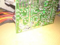
I have opened up the pc supplies. The 0V output of the SMPS is indeed connected to the chassis and earth.
Im leaving the chassis connected to earth for safety.
The PCB 0V and some small filter capacitors are grounded via the mounting holes on the PCB.
I can insulate the PCB mounting holes from the chassis to prevent connection of the two grounds.
My questions are:
There are 4 screws holding the PCB into the PSU chassis. two of the the screws are not connected to the other two or each other by any track on the PCB, they are grounding some fat blue disc capacitors that look a bit like inrush limiters.
If I remove the ground connections from these low pass filters will this be ok? or will i need to connect them to my 0V?
Am I overlooking any safety here other than fishing about inside an SMPS?
Let me know if im not being clear with my descriptions")
I have opened up the pc supplies. The 0V output of the SMPS is indeed connected to the chassis and earth.
Im leaving the chassis connected to earth for safety.
The PCB 0V and some small filter capacitors are grounded via the mounting holes on the PCB.
I can insulate the PCB mounting holes from the chassis to prevent connection of the two grounds.
My questions are:
There are 4 screws holding the PCB into the PSU chassis. two of the the screws are not connected to the other two or each other by any track on the PCB, they are grounding some fat blue disc capacitors that look a bit like inrush limiters.
If I remove the ground connections from these low pass filters will this be ok? or will i need to connect them to my 0V?
Am I overlooking any safety here other than fishing about inside an SMPS?
Let me know if im not being clear with my descriptions
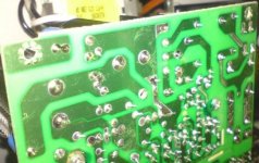
Okay,the holes with the blue caps need to remain connected to the case,and to earth ground.
The ground you want to lift is on the output side. You'll only need to do this to one supply,the one you use for the -V output.(It's positive will be connected to 0V,and it's negative will be -15V.)
You could maybe cut the trace on the PCB,on either side of the hole,and then join them with a short jumper wire,isolating the grounding pad on the board.
Or maybe put an insulating washer of some type under the PC board,and perhaps even use a plastic/nylon screw on that corner.
Maybe other people will have some other ideas.
Again thanks, your advice makes good sense!
I will leave the caps grounded, and insulate the 0V screws as you say. I think a washer and a nylon screw would be ideal but i dont think i can get the right nylon screw.
Im thinking scraping maybe a millimetre round the hole on the track side with a sharp blade to clear nearby track from the screw then use the metal screw with an insulating washer as mentioned.
I hadnt thought that i only needed to do this on the -ve rail PSU, thanks that will save me an hour or 2
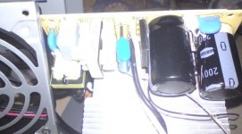
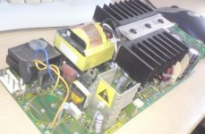
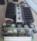
Actually on a side note, the old Lecroy PSU was a very nice quality one with probably much better spec than the PC ones I am using.
See photo attached.
I have used thick copper wire and a PC molex connector to break off my connections from the PC supplies to the scope, i also have a large copper bus bar that serves as a star ground for all 0V connections between supplies.
Will tagging a few thousand uF onto the rail outputs to reduce ripple and some film caps to shunt noise and HF help at all or will it destabilise the SMPS?
I guess the best place if any for filtering is on the +/-15V lines as these surely go to the scopes low noise analogue circuitry.
Attachments
hanging thousands of uF onto the rails of a PC SMPS will most likely make it think the output is shorted.
The Lecroy's 15V rails are probably very low noise. I wouldn't be surprised if they had cleanup post-SMPS regulators.
How much did Lecroy want for a new PSU assembly? What was the main control IC ?
The Lecroy's 15V rails are probably very low noise. I wouldn't be surprised if they had cleanup post-SMPS regulators.
How much did Lecroy want for a new PSU assembly? What was the main control IC ?
Yes the main control chip blew along with the input overvoltage protection diode, the input reservoir caps, and an unsinked T0220 transistor.
The control I.C. that blew is "< 100004 5DW1" quite a flat, green, SIL I.C. standing 1.5ish cm high and 5cm long.
I have been unable to find a replacement.
I think Lecroy wanted either £800 or £1000 for a new power supply which is more than the scope is worth probably.
The control I.C. that blew is "< 100004 5DW1" quite a flat, green, SIL I.C. standing 1.5ish cm high and 5cm long.
I have been unable to find a replacement.
I think Lecroy wanted either £800 or £1000 for a new power supply which is more than the scope is worth probably.
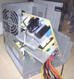
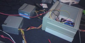
Well ill be bugg**ed.. it worked!
Wires are horribly long and need to increase number of wires carrying 15A to ease the strain on the poor molex.
I might be able to cobble a low noise linear supply for the analogue rails...
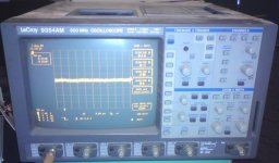
Residual noise with scope lead grounded is under 2mV peak to peak but i think this is a bit poor as it surely should be silent when working fully.
Id love the FFT upgrade but sadly this scope doesnt have the software key to unlock it...Grrr!
But its in there somewhere if anyone knows how to unlock it ??
Some pics:
Wires are horribly long and need to increase number of wires carrying 15A to ease the strain on the poor molex.
I might be able to cobble a low noise linear supply for the analogue rails...
Residual noise with scope lead grounded is under 2mV peak to peak but i think this is a bit poor as it surely should be silent when working fully.
Id love the FFT upgrade but sadly this scope doesnt have the software key to unlock it...Grrr!
But its in there somewhere if anyone knows how to unlock it ??
Some pics:
Attachments
Thanks for your help everybody, Jaycee I know, I think they charge silly prices to the large companies that usually posess these kind of scopes for support.
I going to look into creating a regulator circuit for the 15V rails, at 5A though im not sure how realistic this is.
Roar Malmin, thanks very much for the offer but I simply dont have any money hence the DIY route on this repair
Would a bit of inductance on the 5V rails help?
I have some 35A inductors with ferrite cores, pulled from a big SMPS.
Common mode chokes might be of use?
I could make an LC filter with a few caps to try and clean up a bit. I guess the only thing i cant fix is ripple after the SMPS if too much capacitance will trick it into shutting down.
- Status
- This old topic is closed. If you want to reopen this topic, contact a moderator using the "Report Post" button.
- Home
- Amplifiers
- Solid State
- Powering a feisty oscilloscope