Hi CBS240,
No simulations you mean . No one seems to actually build anything anymore do they. Have always thought it would be quite interesting for the simulation guys to do things the other way around. Build a circuit and measure and test it, warts and all --and then simulate and see if it agrees, and if not why not. I know and am sure you do too, the effect of just moving a wire along a piece of print, how the effect of that is clearly shown on the 'scope. Does the simulator show that ? maybe it does, I don't know. Clamping a transistor to a heatsink, how the added capacitance effects the HF characteristics etc. You have got to build it and get that feel for what happens, and why things happen.
I will have a read at Bobs article. I remember quite a few years ago now when Bob and others wrote about all this in Wireless World. What a shame that magazine ended up the way it did !
Your results look promising, and certainly show the error correction at work. I will try with real speakers as a test load as well, not the B&W's but a pair of Celestion SL100 I still have.
The loss I measured at 16 volts output was around 0.67 dB but this loss varies a bit with absolute level. I must do some more critical measurements when a PCB is done as there are at the moment high resistive losses in the wiring to the outputs.
Going back to Bobs work again, to be honest I really wanted to try the simple approach. To see if there was any major subjective difference in audio quality with the outputs running "free standing" so to speak.
No simulations you mean
. No one seems to actually build anything anymore do they. Have always thought it would be quite interesting for the simulation guys to do things the other way around. Build a circuit and measure and test it, warts and all --and then simulate and see if it agrees, and if not why not. I know and am sure you do too, the effect of just moving a wire along a piece of print, how the effect of that is clearly shown on the 'scope. Does the simulator show that ? maybe it does, I don't know. Clamping a transistor to a heatsink, how the added capacitance effects the HF characteristics etc. You have got to build it and get that feel for what happens, and why things happen. I will have a read at Bobs article. I remember quite a few years ago now when Bob and others wrote about all this in Wireless World. What a shame that magazine ended up the way it did !
Your results look promising, and certainly show the error correction at work. I will try with real speakers as a test load as well, not the B&W's but a pair of Celestion SL100 I still have.
The loss I measured at 16 volts output was around 0.67 dB but this loss varies a bit with absolute level. I must do some more critical measurements when a PCB is done as there are at the moment high resistive losses in the wiring to the outputs.
Going back to Bobs work again, to be honest I really wanted to try the simple approach. To see if there was any major subjective difference in audio quality with the outputs running "free standing" so to speak.
Hi
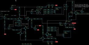
I can't say what sonic differences there may be in using them without EC. I focused on the distorted waveforms and decided it looked terrible. However, I was trying to create an amp with very little distortion so I didn't go any further down that road with any listening tests. Lately I have constructed a follower circuit, a "black box", so to say. It includes a Vbe multiplier and EC. The Vbe multiplier is a separate section so the error amplifiers can be physically located near their related circuit components instead of way out on the heat sink as Bob did. If this circuit was connected to the VAS, the VAS would become the CCS and input bias instead of the way it is now. It's set up to be driven by my function generator at 0VDC. My goal is to eliminate nfb around the "black box" circuit.
I can't say what sonic differences there may be in using them without EC. I focused on the distorted waveforms and decided it looked terrible. However, I was trying to create an amp with very little distortion so I didn't go any further down that road with any listening tests. Lately I have constructed a follower circuit, a "black box", so to say. It includes a Vbe multiplier and EC. The Vbe multiplier is a separate section so the error amplifiers can be physically located near their related circuit components instead of way out on the heat sink as Bob did. If this circuit was connected to the VAS, the VAS would become the CCS and input bias instead of the way it is now. It's set up to be driven by my function generator at 0VDC. My goal is to eliminate nfb around the "black box" circuit.
Attachments
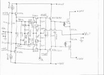
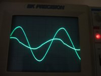
To demonstrate that the gate drive becomes a function of output impedance I measured the output vs the error signal for different load conditions. This was done using an input signal transformer to isolate the function generator from the circuit, grounded the scope reference to the output node, measured circuit GND with ch 1, and ch 2 connected to node A in the circuit, then inverted ch 2 so the phase is correctly oriented to the output.
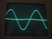
This first picture is with no load. Frequency is 30KHz.
Output is 12V, 5V/div
error signa is 1V/div
This first picture is with no load. Frequency is 30KHz.
Output is 12V, 5V/div
error signa is 1V/div
Attachments
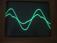
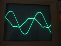
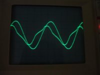
As you can see here at 200KHz with higher frequency the error becomes larger as more drive is needed for the faster change in state. Now you can get an idea of what the error might be like driving a real speaker that exibits different impeadances with different frequencies.
These errors will be included in the output if EC is not employed, this is why I decided to use EC instead of straight hexfet followers. Each stage should be as linear in operation as possible, IMHO, but to each his own.

These errors will be included in the output if EC is not employed, this is why I decided to use EC instead of straight hexfet followers. Each stage should be as linear in operation as possible, IMHO, but to each his own.
Attachments
KLe said:Hi Mooly
Nice and I like this statement ... "More power -- more transistors"
Let us know how it sounds ...
I have built 3 disco/guitar amps using vertical MOSFET's.
100W, 300W and 500WRMS using various pairs of MOSFETs on the output. I use 3 pairs on the 500WRMS amp.
I dont set an exact current through the output resistors but use a scope to tune out the crossover distortion. This results in less standing current.
I just used a bipolar transistors bias cct and this seems to work fine. I tend to over heatsink and dual fan the heatsinks so temperature is not usually a problem
Attachments
Hi CBS240,
Spent about 30 mins looking at this, and I keep refering back to Bobs article ( Must print it out so it's easier to follow ).
It's very interesting, and seems to do what's claimed. I guess your in the same position as me now -- do you build it properly and carry out listening tests.
What I keep thinking is this. When you hang a large speaker on the end of an amp, it behaves as a generator as well. Each speaker of a stereo pair must behave as a microphone and that signal is forced back into the feedback node of the amp. Is that influencing the sound ? Under transient conditions how well does EC cope.
Out of all the amps I have owned, my MOSFET one is by far the best subjectively, and not by a small margin either. It is genuinely more pleasing to listen to, on all levels, depth of soundstage , imaging etc. The worst amps subjectively ( to me ) have been the ones with the highest technical spec. I once owned a Pioneer A80 and the THD TIM etc were unbelievably low. It was a complex circuit as well, FET input stage, current mirrors, cascodes, nested feed back loops, oh and it was class G as well - switched rails, the "low" supply was -/+ 60 volts and the high rail -/+ 75 if I remember correctly. It was very good HiFi but it didn't make music in the way my MOSFET amp does. I have an old Rotel integrated and that is similar as is D. Selfs "blameless class B".
If I go back to any of these it's like listening to a 2 dimensional cardboard cutout in comparison.
So that's where I am at at the moment. To me listening tests are vital, and it may be my circuit above fails on that count -- I will have to see
Similarly with Bobs error correction, ultimately it has to be how it sounds thats the final decider.
Mooly said:Hi Nigel,
Do you find you have to add low value source resistors to equalise the current distribution when you are using multiple FET's or do you match them at all.
I dont use matched MOSFETs.
I use 0R22 source resistors.
I have measured the voltage across them and it does vary quite a bit.
I use IRFP240/9240.
Mooly, this is a great effort on your part. I have quite a few 2SK1058 and 2SJ162 parts, as well as IRF640/9640 and IRFP240/9240.
I just want to hear from you the comparison in sound quality between your proven Lateral MOSFET version and the new Vertical Mosfet version.
I'll make my own PCB layout and try it out ASAP and report the results as well. My comparison would be the Stochino Amp and a heavily modified amp based on Quasi's N-channel. I also have Antony Holton's N-channel, Bengt Olson's N-channel and a single channel of Randy Slone's OPTIMOS, .
The ones listed at the very beginning outclass the rest in terms of sonic quality.
So trying out your amp would be very interesting, considering that I have quite a few good sounding Mosfet amps and many other ordinary sounding Elektor Mosfet amps like the AXL, 500 Watt, Crescendo and Mini Crescendo.
Mooly said:Hi CBS240,
Spent about 30 mins looking at this, and I keep refering back to Bobs article ( Must print it out so it's easier to follow ).
It's very interesting, and seems to do what's claimed. I guess your in the same position as me now -- do you build it properly and carry out listening tests.
What I keep thinking is this. When you hang a large speaker on the end of an amp, it behaves as a generator as well. Each speaker of a stereo pair must behave as a microphone and that signal is forced back into the feedback node of the amp. Is that influencing the sound ? Under transient conditions how well does EC cope.
Out of all the amps I have owned, my MOSFET one is by far the best subjectively, and not by a small margin either. It is genuinely more pleasing to listen to, on all levels, depth of soundstage , imaging etc. The worst amps subjectively ( to me ) have been the ones with the highest technical spec. I once owned a Pioneer A80 and the THD TIM etc were unbelievably low. It was a complex circuit as well, FET input stage, current mirrors, cascodes, nested feed back loops, oh and it was class G as well - switched rails, the "low" supply was -/+ 60 volts and the high rail -/+ 75 if I remember correctly. It was very good HiFi but it didn't make music in the way my MOSFET amp does. I have an old Rotel integrated and that is similar as is D. Selfs "blameless class B".
If I go back to any of these it's like listening to a 2 dimensional cardboard cutout in comparison.
So that's where I am at at the moment. To me listening tests are vital, and it may be my circuit above fails on that count -- I will have to see
Similarly with Bobs error correction, ultimately it has to be how it sounds thats the final decider.
Hi Mooy,
Nice work!
Although I use SPICE heavily, I agree that there is no substitute for building the thing. Similarly, although I rely on measurements heavily, there is no substitute for listening. Interestingly, when I did the EC MOSFET amplifier back in 1983, I did not use SPICE for it at all.
I've always liked the HEXFETs, but we all know that their use comes with a price. The extra Vgs needed to turn them on often translates to higher drop from the rail, unless a boosted supply is used. This can often translate to a bit more cost for a given rated-power amplifier. Because of their high speed, one also does indeed need to be more mindful of local parasitic oscillations. I have found that a proper combination of gate stopper resistor and gate Zobel network stabilizes them well without throwing away too much of their speed. I have always driven them with BJT emitter followers rather than directly from the Hi-Z VAS node. It is also very true that the vertical MOSFETs do need some thermal bias compensation, although they tend to be more thermally stable than BJTs.
I have made HEXFET MOSFET amplifiers without error correction and they sound very good, even though their THD-20 is in the 0.02% range.
Good luck with this project.
Cheers,
Bob
Hi Sam,
PCB next ! Actually I just want to try a couple more things out first including driving real speakers as CBS240 mentioned.
Got as far as hooking it all up yesterday for some serious measurements, but ended up going for a walk by the canal
Have you actually built the lateral FET version. I am sure you would not be disappointed sonically.
Regards Karl
Hi Bob,
Thanks for taking an interest in this. It's my first "play" with HEXFET's for linear audio and yes, I am impressed.
I might try your suggestion, and look into the use of followers for the gate drive.
What has surprised me most, is how stable they actually are given only modest precautions, certainly in this configuration.
Have to see how it all sounds
Thanks again Karl
Mooly said:So here it is, very much work in progress, but with a few actual shots to show what really happens.
What I really want to know ? Anyone --- how does taking the outputs out of the loop affect sonics.
Each to their own, but running the output stage out of the loop without class A bias will give you an awfull lot of crossover (nasty high order) distortion with these devices. Full amplitude distortion may be in the vicinity of 0.5-1%, worse with decreasing amplitude.
- Status
- This old topic is closed. If you want to reopen this topic, contact a moderator using the "Report Post" button.
- Home
- Amplifiers
- Solid State
- New Design-HEXFET Poweramp. Sonic benefits of this approach.