I was going to add some of these shots to another thread after a D.I.Y. member contacted me regarding their latest build, and he commented that all the amps he had constructed ( including my design on this Forum ) sounded totally different ( by the sound of it very very different ). Having seen the layout and pictures I couldn't help thinking that layout was as much to do with it as anything.
As it may help others I've decided to put it in it's own thread.
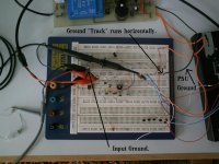
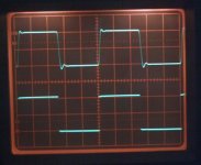
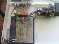
First shot then is the amp--- and how not to do it --- but as this is similar to many "veroboard type " constructions I think it valid.
The design is based on my own MOSFET amp but this is different, I've been playing around with some HEXFET's and this is the result so far.
As it may help others I've decided to put it in it's own thread.
First shot then is the amp--- and how not to do it --- but as this is similar to many "veroboard type " constructions I think it valid.
The design is based on my own MOSFET amp but this is different, I've been playing around with some HEXFET's and this is the result so far.
Attachments
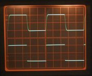
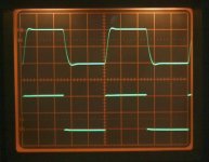
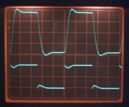
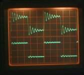
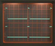
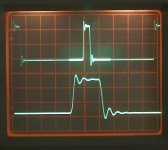
This time with the output returned to the wrong point so that the input ground is "contaminated" by the output current.
This is the only thing to have been changed -- compare the traces to the one above. Note the amplitude of the output now !
This is the only thing to have been changed -- compare the traces to the one above. Note the amplitude of the output now !
Attachments
This was all a bit of fun on my part, I wanted to play with some HEXFET's, but it seemed a good opportunity to put this down so to speak. On a side note the amp design I use (single ended input) is very very stable and an amp with a differential input pair would give far more extreme results than this, with this type of layout . Try as I might it was hard to provoke this lash up into oscillation. If you look at the first shot you will see there is NO decoupling on the plugboard at all, and still it's stable.
Hi Andrew,
Do you mean in Posts 4 and 6. The output current is contaminating the input ground.
It's not the last word in correct construction of course, I just thought it may help some DIY' ers. For anyone without test gear, it shows the kind of pitfalls that can arise--and we have all done it, Im sure. I know I have.
Hi
I use breadboards much less than I use to. They are pretty much used as quick connecting sockets or for simple test circuits. Any circiut that you intend to have operate at high (RF) frequencies, old worn out solderless breadboards just will not do. Vero-board is the stuff for amplifier prototypes. It is actually quite handy for SMD circuitry, specifically SOT-23 and cheap 603 or larger resistors. It is surprisingly easy to change the circuit around. The solder is "sculpted" around the circuit components so building a symmetrical circuit with a symetrical layout is easy, just place the opposing transistor upside down.") I've even used SOIC-14 components in this manner. If you cut the small pads around the holes in two then the SOIC pins line up perfectly.
I've even used SOIC-14 components in this manner. If you cut the small pads around the holes in two then the SOIC pins line up perfectly.
ex 1
ex 2
ex 3
As for long term reliability? Probably not that great. Solder does dry out and crack. However, I will say that this amplifier is still in perfect operation after over 8 months.

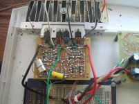
The input filters are on the vero-board. Notice there is a separate wire for the output's decoupling caps to the "star".(thick green wire from veroboard) The input GND is connected to the source common GND, then to the star.
Note: this is 1 channel, SE input, BL output so the speaker doesn't connect to GND. If it did, it would ground at the star via another separate wire. Of course in this circuit, any load from output(s) to GND will miss-balance the bridge and it will not remain stable. But then that's not the intended output anyway.
I use breadboards much less than I use to. They are pretty much used as quick connecting sockets or for simple test circuits. Any circiut that you intend to have operate at high (RF) frequencies, old worn out solderless breadboards just will not do. Vero-board is the stuff for amplifier prototypes. It is actually quite handy for SMD circuitry, specifically SOT-23 and cheap 603 or larger resistors. It is surprisingly easy to change the circuit around. The solder is "sculpted" around the circuit components so building a symmetrical circuit with a symetrical layout is easy, just place the opposing transistor upside down.
I've even used SOIC-14 components in this manner. If you cut the small pads around the holes in two then the SOIC pins line up perfectly.ex 1
ex 2
ex 3
As for long term reliability? Probably not that great. Solder does dry out and crack. However, I will say that this amplifier is still in perfect operation after over 8 months.
The input filters are on the vero-board. Notice there is a separate wire for the output's decoupling caps to the "star".(thick green wire from veroboard) The input GND is connected to the source common GND, then to the star.
Note: this is 1 channel, SE input, BL output so the speaker doesn't connect to GND. If it did, it would ground at the star via another separate wire. Of course in this circuit, any load from output(s) to GND will miss-balance the bridge and it will not remain stable.
But then that's not the intended output anyway.Attachments
Hi mooly,
Yes, all you need is ossiloscope...dear.
great result showing, thanks for your test. i used gnd into seperate line. as i don't have ossiloscope so i can't msure those errors. my amp is woking as normal, may be there could be some errors hiding there but they are not too bad. i made quite some times ago and it is still working well. as "CBS240" describe about his exp, i am agreed on it. i also agree with you totally. we are just hobbiest so can't expect much from our amp as we don't have any proper equipment to test. we hardly have one multi meter some one even don't have this. honestly tells you, i even don't know how to use ossiloscope. i am intending to buy a cheap one for my self. still looking for it. may be you guys can tells, which will be cheap and easy to use.
Thank you for your test result. we all can learn from here.
best regards
michael
Hi CBS240,
I like the SMD on the Veroboard -- for prototyping thats brilliant--it just goes to show what you can achieve when you set your mind to it. Must try that next time I want to use SMD in a prototype.
I have always used breadboards from the early days (Remember the T-Dec and the S-Dec), you needed parts with legs half a mile long with those and I/C's were out of the question.
And of course today most wouldn't even do this at all, it would be the simulator, and hours spent trying to flatten out that little kink somewhere, which would probably change into something else anyway if it were actually built.
No I.M.O. there is no substitute for hands on, to be able to instantly see the effect of changing a component or running a wire differently teaches you such a lot.
And of course all these comments on layout apply even more to the chip amp devotees. Those things really can bite back
Hello Michael,
"Just a hobbiest so you can't expect much from your amp" NO NO NO. You can't say that
I know you have made many amps (probably more than most on this forum), but you need to progress, learn new skills.
You do need a 'scope and function generator. The cost needn't be that great. Anyway how much did those 20 or so HEXFET's cost that your dicky soldering iron zapped And learn to make PCB's.
You need to measure and test all that you build. If you think one amp sounds different to another at least you will know that nothing untoward is going on- not oscillating at HF, or no crossover distortion etc etc.
So if it were me it would be 'scope and generator next Not another Aleph just yet (not this week anyway )
"Just a hobbiest so you can't expect much from your amp" NO NO NO. You can't say that
I know you have made many amps (probably more than most on this forum), but you need to progress, learn new skills.
You do need a 'scope and function generator. The cost needn't be that great. Anyway how much did those 20 or so HEXFET's cost that your dicky soldering iron zapped
And learn to make PCB's.You need to measure and test all that you build. If you think one amp sounds different to another at least you will know that nothing untoward is going on- not oscillating at HF, or no crossover distortion etc etc.
So if it were me it would be 'scope and generator next
Not another Aleph just yet (not this week anyway )hi mooly,
i would like to buy a osciloscope, a simple one. i am not shure which will be btr for me. also need know do i need any others addaptor with it? like seperate probe or some things. Today i went to electronics market to see the pcb making...yes now i am already trying to learn to draw pcb. soon will make one. pcb one problem is, if there is need to change, very dificult right? but there are many good points rely on pcb.
anway need to learn skils for making amp. i like to making amp as i have resources so should have one osciloscope right?.....must have one...
what is 'scope and generator"?
best regards
michael
Mooly, with a bit of observation, you will see that one can just as easily polute low current parts of the power rails... by not routing them properly...
Lately I am starting to pay alot more attention to the whole current loops when doing layouts.... I have to thank the person that mentioned micro cap...it realy makes my life easier.
Lately I am starting to pay alot more attention to the whole current loops when doing layouts.... I have to thank the person that mentioned micro cap...it realy makes my life easier.
Hi Nordic,
Absolutely !! Every piece of wire, every piece of print is a "potential" source of a problem.
It's a real eye-opener to actually see the effect of moving a connection a few centimeters along a piece of print.
Nordic said:Mooly, with a bit of observation, you will see that one can just as easily polute low current parts of the power rails... by not routing them properly...
Absolutely !!
Every piece of wire, every piece of print is a "potential" source of a problem. It's a real eye-opener to actually see the effect of moving a connection a few centimeters along a piece of print.
- Status
- This old topic is closed. If you want to reopen this topic, contact a moderator using the "Report Post" button.
- Home
- Amplifiers
- Solid State
- Oscillograms/Testing, and why layout matters.