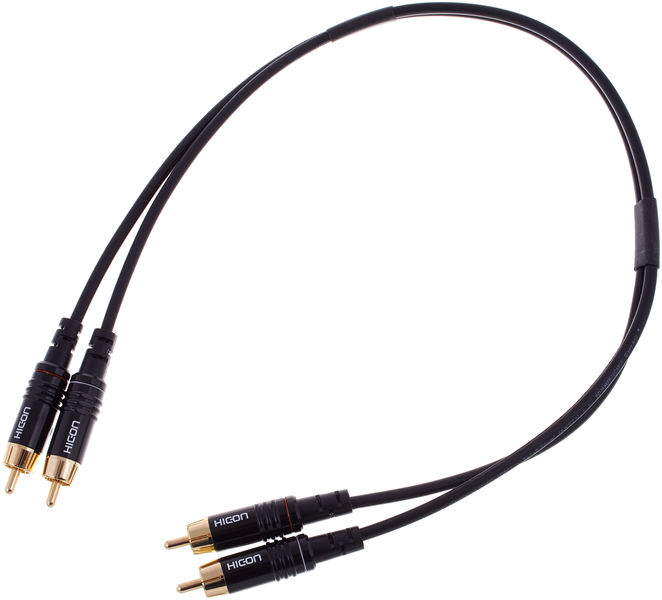
Hum problems can have their origin in the RCA cable having a "bifid" shape like a tongue snake, the separated ground conductors creating a ground loop.I could make it that way but the input cable of one channel will be very long and will run near the trafo
A symetrical implementation with heatsinks on both sides of the case with the transformer at the center may be nice looking, but, albeit very often used, is electronically not optimal at all.
Can you explain bifid shap so i can correct it
"Bifid" applies to the sphape of a snake tongue.
When connected to an amp with distant sockets, the cable shields are not parallel for a not-negligible length and form a ground loop.
Here is a typical "bifid" stereo RCA cable. :
A bifid tongue :
An externally hosted image should be here but it was not working when we last tested it.
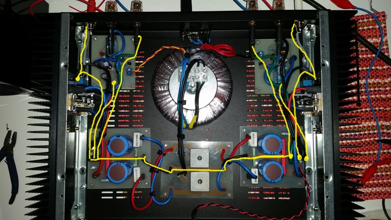
this is my p3a
in yellow are shown gnd traces.
I tried to:
1. disconnect the gnd from one rca socket;
2. put together the gnd of both the rca socket and go to main gnd with one wire;
3. connect each rca gnd individually with a new wire from the plug to main gnd;
4. invert secondary cables of the trafo;
the huum always remains the same. it only disappear with:
A. no input connected;
B. only one channel input connected;
C. inputs shorted.
what to do?
Try a different source?
Try different RCA cables?
Is it 50Hz / 60Hz hum or 100Hz / 120Hz?
yes, i tried with 3 different rca cables, with portable cd player, smartphone, table cd player, with preamp and also without it.
It's more likely a 100/120hz hum,
^ While this would suggest electrostatic pickup, B) clearly points towards a ground loop issue. Complete your image from post #24 with an RCA cable and source, and you'll find where it is:
Source --> L input GND --> L amplifier board --> power supply --> R amplifier board --> R input GND --> source.
Loop area spans a large part of the amplifier and a bit outside, including the mains transformer. Not good.
I'm afraid there's only one way to save this one in a somewhat economic fashion, and that's going fully dual mono, with either two separate mains transformers or at least one transformer with two isolated secondaries, and a chassis ground to circuit ground connection that's not too low in impedance (maybe 100R || 100n for each channel).
Otherwise we'd be looking at a major rearrangement of the insides, at which point you might just as well scratch the thing.
^ While this would suggest electrostatic pickup, B) clearly points towards a ground loop issue. Complete your image from post #24 with an RCA cable and source, and you'll find where it is:
Source --> L input GND --> L amplifier board --> power supply --> R amplifier board --> R input GND --> source.
Loop area spans a large part of the amplifier and a bit outside, including the mains transformer. Not good.
I'm afraid there's only one way to save this one in a somewhat economic fashion, and that's going fully dual mono, with either two separate mains transformers or at least one transformer with two isolated secondaries, and a chassis ground to circuit ground connection that's not too low in impedance (maybe 100R || 100n for each channel).
Otherwise we'd be looking at a major rearrangement of the insides, at which point you might just as well scratch the thing.
ok. i think i can't put a second trafo here in this chassis.
now I just tried to connect the Main EARTH ,and I tried only connecting it to the chassis and connecting it also to the GND. nothing has changed.
so now, my transformer has 2 isolated secondaries (0-24/0-24).
can you tell me how to solve this issue?
many thanks
indeed. The layout drawing shows input signal as a single wires that becomes two wires next to the amplifier PCB. The output has two wires going in different directions. One must keep all Flow and Return of a circuit TOGETHER as a close coupled pair or as a twisted pair. Do not split your wiring into single wires.Looks like input ground goes to the amplifier and then to star ground - running close to the trafo all by it's lonely self - better to have all wires in pairs and either twisted or be coax where the loop area is small.
Attached is a proposed wiring diagram I posted in my TGM8 thread to show the pairs of wires for twisting.
No !could be a solution to connect the rca gnd directly to the psu insted of connecting it to amp gnd?
the input cable from the RCA/Phono socket must be a close coupled pair all the way to the amplifier PCB.
Use a two wire Pair for EVERY circuit. Each module has TWO wires that connect to the next module. That connection MUST be done as a two wire connection. You can use coaxial using the braid as the Return connected at both ends, or use a twisted pair with both wires connected to the terminations at both ends, or a close coupled pair again with both ends connected at both ends. There are no exceptions.........................
the huum always remains the same. it only disappear with:
A. no input connected;
B. only one channel input connected;
C. inputs shorted.
what to do?
I'll repeat:
Use a two wire Pair for EVERY circuit
When building a stereo power amplifier one usually ends up wiring in a loop in the return/grounding wires. Solve this by invoking the D.Joffe HBRR/HBRL to attenuate the interference current.
Last edited:
Why two separate filtering plate with a single transformer? This is good in dual mono
You have to climb the four capacitors after the sets rectifier bridges and power amplifiers by two (one positive, one ground and one negative).
no problem in making this...but do you think that's the issue?
In the old layout I had only a big plate with 4 x10kuf capacitors after a single rectifier, the same layout you are talking about right now.
>From that board I supplied both channel ...but the noise was Always there
At the beginning, when I start mounting I tried just one channel each time, and didn't have noise, as now if I connect only one channel or input shorted. the problem is when both channels are connected
...................................
When building a stereo power amplifier one usually ends up wiring in a loop in the return/grounding wires. Solve this by invoking the D.Joffe HBRR/HBRL to attenuate the interference current.
Read Joffe and HBRR/HBRL......................
At the beginning, when I start mounting I tried just one channel each time, and didn't have noise, as now if I connect only one channel or input shorted. the problem is when both channels are connected
Andrew you are talking about to use a double cable in place of the single cable, am I right?
I have to unmount all the wiring and make it again...I'll try this evening
But, what is the "right" way for wiring this amp? If I understood correctly, the issue is created with rca connections...so there isn't a ground loop but a captation of noise! right?
I have to unmount all the wiring and make it again...I'll try this evening
But, what is the "right" way for wiring this amp? If I understood correctly, the issue is created with rca connections...so there isn't a ground loop but a captation of noise! right?
Source --> L input GND --> L amplifier board --> power supply --> R amplifier board --> R input GND --> source.
Most stereo amps are wired like this, and still most of them don't have a hum issue. Why? I have wondered about this many times...
I have a P3a laid out similar to yours with input RCA sockets at opposite sides of the case.
I also had a similar hum problem to yours.
I picked up an idea from the Leach amp site about an improvement.
You might want to try something similar, it is a long way from optimum, but it was better than the hum I had.
What I did was this: on one of the RCA jacks, cut and set off to the side only the ground braid between that jack and the amp board for that channel, then run a jumper wire from the ground of that jack to the ground jack on the RCA for the other channel.
The hum should either get better, or not change. In my case it got considerable better, but not as good as it should be as you are running the ground thru the other board.
If it helps, fine, if not it is not much trouble to reconnect it back to the way it was.
this might buy you some time to rework your ground system for better performance.
I have a P3a laid out similar to yours with input RCA sockets at opposite sides of the case.
I also had a similar hum problem to yours.
I picked up an idea from the Leach amp site about an improvement.
You might want to try something similar, it is a long way from optimum, but it was better than the hum I had.
What I did was this: on one of the RCA jacks, cut and set off to the side only the ground braid between that jack and the amp board for that channel, then run a jumper wire from the ground of that jack to the ground jack on the RCA for the other channel.
The hum should either get better, or not change. In my case it got considerable better, but not as good as it should be as you are running the ground thru the other board.
If it helps, fine, if not it is not much trouble to reconnect it back to the way it was.
this might buy you some time to rework your ground system for better performance.
Hi gch53
I tried it before (if you read some posts ago you can see the proof has been done) and nothing had changed.
NEWS
the proof i made was disconnecting dc protection in order to see if they are part of the issue. THEY are not, noise is Always there, BUT....when I power off the amp, it countinues to sound for 10-15 seconds, and there is not noise....
- Status
- This old topic is closed. If you want to reopen this topic, contact a moderator using the "Report Post" button.
- Home
- Amplifiers
- Solid State
- Rod Elliot P3A amp noises