Toroids.
Primary Inside or Primary Outside?
This is a quote from an interview with Richard Dunn of (now defunct) NVA.
"We now use an Avel Lindberg., which we consider to give us the sound we want. Mark Levenson also uses their transformers. They are also very compact for their V/A rating because they have found a way of winding the primary outside the secondary, which is actually more difficult. A majority of toroids secondaries are would outside the primary, for safety sake, because when the primary is outside the secondary, if you damage the transformer, you've got mains there, if the insulation goes, so that is why most people wind the secondary to the outside. But this design of transformer is better, you'll lower impedance if you wind primary outside the secondary. "
Any comments?
focus on transformers
I agree with only one of these. Of the remaining three, one is irrelevant, one is not part of the actual transformer, and the other is very application dependent: in fact it is true in one application but false in another. Optimal transformer choice is still very dependent on the circuit it is powering and an order of importance for design parameters will be very dependent on the circuit application. It is just not as cut and dried as one might think. Maybe a good starting point for understanding transformers
design parameters would be:
http://www.avellindberg.com/pdf/avel_tech_notes.pdf
http://www.plitron.com/pages/technote.htm
"'They are also very compact for their V/A rating"
A common sign of high flux density and not an asset for sonics.
From the Plitron site:
The key to all toroidal transformer advantages is its efficiency. And the key to its efficiency is the core. The core is a continuous strip of grain oriented silicon steel, wound like a clock spring, under tension. It is annealed to relax the molecular structure which ensures that all grains are in the magnetic direction (unlike the old standard EI, with about 40% in the wrong direction). There is no air gap, resulting in a stacking factor of 97.5% of its weight. Since all the windings are symmetrically spread over the entire round, gapless core, a higher flux density is possible (toroidal transformers operate at flux densities of 16 to 18 kilogauss, while traditional EI transformers operate at 12 to 14 kilogauss). The magnetic flux is in the same direction as the grain oriented silicon steel core, thus achieving very high electrical efficiencies. Typical efficiency figures for toroidal transformers are 95% (e.g. 18kVA at 98% efficiency).
Fred Dieckmann
I will try to elaborate your reply. Please correct me if I misinterpreted you. Your list:
1. core flux density (lower is better)
2. DC blocking/inhibiting (not a significant function of the transformer and better handled by an external passive addition)
3. quiescent current (application specific)
4. conductor thickness (completely irrelevant)
All other posters, please use the format above in your reply. It is concise and will make it easier for later analysis.
"I will try to elaborate your reply. Please correct me if I misinterpreted you."
Yes, you have definitely misinterpreted me...... Please read my post again.
Some more technical articles are at:
http://www.plitron.com/pages/sitemap.htm
I think the technical content below is required reading before discussing the alternative approaches. The reasons that toroidal
transformers are designed like they, are will became much clearer.
The trade offs can be explained only after the fundamentals are understood.
http://www.avellindberg.com/pdf/avel_tech_notes.pdf
http://www.plitron.com/pages/technote.htm
Fred Dieckmann
I'm sorry you felt I misinterpreted you. I did read the links and did not find anything in them that contradicted my interpretation of your post. Which of the four on the list did you think was irrelevant? Which was the one you agreed with? Since you didn't specify it in the format provided, I extrapolated your list from your previous posts in this thread. I read your posts quite intently, I assure you")
Please trust my method, I promise you it will keep us from meandering around the interactions of these issues on the sonics.
I'm sorry you felt I misinterpreted you. I did read the links and did not find anything in them that contradicted my interpretation of your post. Which of the four on the list did you think was irrelevant? Which was the one you agreed with? Since you didn't specify it in the format provided, I extrapolated your list from your previous posts in this thread. I read your posts quite intently, I assure you
Please trust my method, I promise you it will keep us from meandering around the interactions of these issues on the sonics.
I'm sorry you felt I misinterpreted you.
I was puposely vauge to see if I had gotten my point across. Evidently I did not come close and the shortcoming is on my side. I think I have said pretty much all I have to say and am more interested in others experiences and theories. I do plan to explore the diodes roles in the supply and their interaction with the transformer. I need to do some more research and some measurements which I hope to report on in the high speed diodes thread. I urge everyone to read the imformation on the sites below which offer very clear and well written articles on transformer design.
http://www.avellindberg.com
http://www.plitron.com
Nania,
Fred seems to be teasing you a little.
One thing, that may just be the words you've chosen, concerns point 2. All transformers block dc. The thing Fred may be talking about is how dc current in the primary or secondary may affect the linearity and saturation headroom of the transformer core. So perhaps the desirable characteristic is "dc tolerance".
Incidentally, it would be better not to use a core at all in this respect: an air-cored power transformer would be really good and wouldn't saturate. The trouble is that it would need to have a vast number of windings and would become impractically large. I wonder if there is a better material for cores other than laminated steel. Fred?
BAM
traderbam
Well, I used a term which I thought describes the effectiveness of how well it blocks it and Fred Dieckmann has indicated in his posts that this would be handled better with an add on but that doesn't make it irrelevant does it? I don't know if using the term "DC tolerance" is an improvement to describe this parameter but I do know that interpreting Fred might deserve its own threadAll transformers block dc.
Hi,
Yup.
IMO Fred meant leakage current.
Cheers,
There is no "how well" there is just "not at all".
Yup.
IMO Fred meant leakage current.
Cheers,
"DC tolerance" is an excellent term. More specifically tolerance to DC current in primary winding. Interestly the difference in weight for a Plitron 1000VA standard transformer and a 1000VA designed for low noise is 6 Kg. for the standard vs. 16 Kg. for the low noise version designed to "remain quiet even at 10% high line with 250 mV DC voltage in the mains." This seems to fit exactly with the idea of low flux density being a desired attribute. As stated the transformers the noise seems to be related to the line voltage and prescence of DC. The vast weight difference would appear to be from the amount of core material used, The same effect can be acheive with two transformers in series. I see at least one commercial manufacture seems to share veiw point conserning flux density presented here. But as they state "The LoNo Audio Power Transformer Line of toroids is designed for demanding high-end audio amplifier applications." Anyone here still think we are making this stuff up? Jeff Rowland was dealing with these issues ten years ago.
http://www.plitron.com/pages/Products/Audio/lonopwr.htm
"doesn't make it irrelevant does it?"
You are applying that remark to the WRONG TOPIC....
Excuse me while I return to perusing the Plitron site. Seems that they build some excellent TUBE OUTPUT TRANSFORMERS also.
That one was for Frank.
"Ah. But leakage current is an AC current isn't it?"
Can be anthing from DC to RF. Kuei Yang Wang introduced the topic in reference to RF noise coupling trough the winding capacitance.
Fred Dieckmann said:" Interestly the difference in weight for a Plitron 1000VA standard transformer and a 1000VA designed for low noise is 6 Kg. for the standard vs. 16 Kg. for the low noise version designed to "remain quiet even at 10% high line with 250 mV DC voltage in the mains."
This is how big Plitron low noise, 1.5kVA toroid is.
I tried to use it for balanced AC power configuration (since it had quadrupled 30V secondaries) but actually it degraded the sonics in my setup. I was actually happy for that, since the transformer was $600CAD to have
Attachments
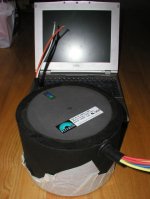
XFORMER-FILES.
Hi,
Yes, sir.
I know that very well...the engineer that developped those is Menno Van der Veen.
He's Dutch and all the studies have been published in Dutch audio mag "Audio & Techniek" some 10 years ago.
Applying the requirements for a good OPT to a powerxformer however is not what you want to do.
If we take a classic OPT (not a toroid) you will see that the core materials required are almost opposite to what you want from a powerxformer.
That is what I meant by the " contradictions" in a previous post.
If you don't agree with that I'd welcome an explanation, from any of you...
Cheers,
Hi,
Seems that they build some excellent TUBE OUTPUT TRANSFORMERS also.
Yes, sir.
I know that very well...the engineer that developped those is Menno Van der Veen.
He's Dutch and all the studies have been published in Dutch audio mag "Audio & Techniek" some 10 years ago.
Applying the requirements for a good OPT to a powerxformer however is not what you want to do.
If we take a classic OPT (not a toroid) you will see that the core materials required are almost opposite to what you want from a powerxformer.
That is what I meant by the " contradictions" in a previous post.
If you don't agree with that I'd welcome an explanation, from any of you...
Cheers,
I think I understand the objection to list issue #2. I was looking at it from the point of view of the end result but perhaps it is better to look at this from how much DC the transformer can tolerate before degrading sonics. Very well, the edited list:
1. core flux density (lower is better)
2. DC current tolerance (higher is better)
3. quiescent current (application specific or possibly irrelevant)
4. wire thickness (thicker is better or application specific)
I would like to note that perhaps it would be better to have a transformer that will inhibit the DC from getting in the coil in the first place but measuring its immunity to DC will work just as well for the time being. Are we closer to agreement now?
Thanks Steve!It's an electrostatic shield used to amoeliorate problems caused by interwinding capacitance (the capacitance between the primary and secondary windings). Interwinding capacitance allows high frequency garbage at the primary to couple to the secondary.
Peter Daniel said:
This is how big Plitron low noise, 1.5kVA toroid is.
I tried to use it for balanced AC power configuration (since it had quadrupled 30V secondaries) but actually it degraded the sonics in my setup. I was actually happy for that, since the transformer was $600CAD to have
Perhaps proving that old adage "its not how big it is but what you do with it".........
And you all thought I had given up humorous post completely.
Nania, I will elaborate (following Fred Dieckmann's good approach) on this a bit. I think it is actually impossible to compare how 2 "identical" x-formers ("xf" for short) which have different Iq affect sound, because as Fred wrote, this means that they are not identical. Because of this, i believe that the only way to tell if Iq is irrelevant or not, is to try to understand what causes this Iq in the first place. So, starting from the definition of Iq (and remembering that we are talking about non perfect i.e. real xf) i will go on.3. quiescent current (application specific or possibly irrelevant)
"Iq" or excitation current is the current running through the primary winding , when the primary is connected to a constant voltage source supplying a voltage "V1", and the secondary is open (not loaded).
Primary's inductance finite value produces an electromotive force "e1" such that e1=-V1. This is achieved through the magnetic flux "flq" that is running through the core. If Iq would increase for some reason, so would flq, which would increase e1 in order for e1=-V1 to be preserved. This self balancing mechanism, leads to a minimum Iq. But how much is this minimum? As small as is adequate to let a stable minimum magnetic flux running into the core (in other words, to "magnetise the core, thus the more technical name "magnetising current" for Iq). This magnetic flux completing it's magnetic path, has to fight some losses, namely the eddy current and the hysteresis loop losses ("iron losses"). The higher these losses, the larger the Iq that needs to "feed" the flq for to keep it stable. V1*Iq= Iron losses (in Watts).
I believe that neither high eddy currents, nor high hysteresis loop core losses can be related to any benign sonic effects. Thus my oppinion is that the lower the quiescent current, the better. Always. ( Incidently, V1/Iq gives the measure of primary's impedance)
Another form of xf losses are "copper losses". It is the power wasted due to ohmic resistance of the windings. It becomes maximum when the xf is heavily loaded. [It can be measured as follows: Man shorts the secondary and starts increasing primary's V1 from V1=0 up to V1=Vk, at which Vk (approx. 2%-5% of primary's nominal voltage), primary and secondary currents reach their nominal values. Since secondary voltage V2=0, it follows that e2 (electromotive force of secondary) is also zero. This means that magnetic flux is negligible, thus iron losses are negligible too. V1*I1 gives the copper losses (in Watts)]4. wire thickness (thicker is better or application specific)
I think that the only but important beneficial -side- effect of high copper losses is the attenuation (smoothing?) of the capacitors charging current on the secondary and the subsequent imbalance of the xf parameters ( I expressed my view on this in the "What fuse for gainclone" thread). I may speculate that if thermal limits are not reached, thin wires may work for us.
Regards
George
gpapag
Now we're cooking! This is an excellent post but we still haven't uncovered the mystery of which of the four listed items Fred thinks is irrelevant. So thinner wire used in the core will create resistance under load that may have sonic benefits, very interesting. Are there any other issues besides the four we mentioned that may effect sound? I noticed that you used the traditional "I" to represent the amperes measured in quiescent current. I used Aq because I didn't want to use "Iq" but I will follow the wishes of the participants.
For all the other members participating in this thread, please provide a list with the following format, it'll make it a lot easier to keep track of who said what. Work in progress list as it now stands:
1. core flux density (lower is better)
2. DC tolerance (higher is better)
3. quiescent current (lower is better or application specific)
3. wire thickness (application specific)
- Home
- Amplifiers
- Solid State
- What makes a good audio power transformer?