Here is an idea I am trying. I want to create a gain block where the loop gain can be varied continuosly between 0db (zero loop gain) and some arbitrarily high value (loop stability notwithstanding).
The idea is that you can change the loop gain on the fly and then see if an audible difference can be heard.
Here is my 1st shot at it. A pretty conventional CFA topology using a Hawksford VAS stage and diamond buffer.
The loop gain is varied by adjusting the value of R18 (c.f. Hawksfords paper where he mentions this). With R18 set to 1 meg (about 65db OLG), the 20k THD simulates at <1ppm and with R18 set to 1k the 20k THD is about 0.015% - so this would I guess discount distortion as a key reason for the difference in sound, if any is detectable. Of course, some work is needed to ensure the circuit is stable across such a wide loop gain range.
Edmond, since you are the resident CFA king, maybe you can comment on the approach or offer some insights.
BTW, if you insert a cascode in the collectors of Q13 and Q14, you can get the 20k THD down to about 250 parts per billion (with R18 set to 10k - so about 40db OLG at 20kHz).
Attachments
Hi Bonsai,
Me, the CFA king? That's too much honor.
Anyhow, of course you can do it that way, but some people might argue that your circuit has a different topology than most amplifiers have, so listening tests are not representative.
For example, your circuit is symmetrical, therefore (almost) no even harmonics will show up, while asymmetrical designs will produce more even harmonics. In other words, the distribution of the harmonics will be quite different.
Perhaps, you may also build a second circuit, that is, a asymmetrical one, or just start with an existing high NFB amplifier and load the VAS output with a pot.
Probably you know already what I think about the low vs high NFB controverse, if not, look here:
http://www.diyaudio.com/forums/showthread.php?postid=1540288#post1540288
As for the additional cascodes, your right, they will lower the distortion even further. BTW, this is exactly what I have done with my latest design.
Cheers,
Edmond.
Edmond, thanks for the feedback.
I am specifcally trying to remove the 'distortion' part of the sound - this is why I mae the statement about 20kTHD distortion with heavily loaded VAS being 0.015% and therefore not a consideration.
I guess, I would like to see if, in a circuit with inherently very low open loop distortion, what, if any, changes to the sound will be by applying feedback.
I know your views on ZGNF designs, and personally I have no beef with feedback. I use it myself.
However, if we can conduct an experiment where we can vary GNF, it would help illuminate the discussion and perhaps settle a few arguments don't you think?
Hi Bonsai,
I will appreciate all your effort to shed more light on this topic. But frankly speaking, I'm lacking the enthusiasm (and time!) to discuss the matter with the 'other camp', because I'm afraid that they will be completely deaf to arguments from the high NFB camp.
Besides, I'm hopeless behind schedule with other things like the PCP amp and my website, sorry.
Nevertheless, please go on with your experiments and I will follow them with great interest.
Cheers,
Edmond.
Loading the VAS is a little more complicated than it looks at 1st sight
it's "obvious" that you reduce the gain by heaver loading - it is less obvious that you also reduce the output impedance - which then causes lower "interface distortion" with the next stage which presents a nonlinear dynamic load to the VAS
for the common situation where the input current nonlinearity of the output/driver stage is the larger distortion component the reduced drive impedance can be nearly as effective as the unloaded VAS higher (Voltage) loop gain in reducing this distortion
at a minimum a "fair" comparison would require a gain trimmable block with fixed input and output impedances regardless of gain setting
and then you have to decide what is "fair" when it comes to loop gain compnsation as you vary gain
I don't see the critical ".options plotwinsize=0" directive in your schematic - this turns off Ltspice' default lossy data compresson that makes distortion measurements futile - I always include the directive on each schematic .asc rather than try to remember to change control panel settings
I find it simpler to attach Ltspice .asc files by just copying them, renaming the copy with a extra ".txt" extension, maybe
newer defaults in Vista make this too difficult - I'm avoiding Vista machines at work as long as I can
Hi JCX,
Although I generally agree with you, one remark about the VAS output impedance vs the input impedance of the OPS and the effect of loading the VAS:
Looking at the blameless amp, for example, VAS-Zo= 500 Ohm and OPS-Zi = 200kOhm at 1kHz. So I don't think that, at least in this case, the "interface distortion" will be much lower if the VAS is loaded by an external resistor of say 5kOhm. The DC open loop gain however, is decreased by ~20dB.
@Bonsai,
What do we do with unity gain frequency of the NFB loop? Keeping it constant or varying it with the same amount as the DC loop gain?
Cheers,
Edmond.
granted there are lots of possible scenerios,
I was thinking more about C loading of the VAS to establish the dominant pole vs Miller C compensation, another example exagerating these effects is directly driving Mosfet output Q without intervening buffers
also I'd consider 20 KHz as the "design" frequency since I believe available negative feedaback at 1 KHz can be so high that resloving any effects there is a measurement challenge
I've found that this circuit needs a Miller cap of 100pF or more to have enough phase margin at low gains. And since it's all pretty much class A there is not that much distortion to be reduced by feedback anyway. At higher signal amplitudes and/or heavier load the picture changes when the outputs are starved of current or even enter class B.
- Klaus
- Klaus
Bonsai,
If your objective is to vary the magnitude of the feedback, whilst keeping the loop GBP the same, why not make a servo and vary the servo gain? So make a fixed gain amp. Add a servo. Vary the servo gain.
That way you don't mess with the intrinsic distortion in the amp.
Brian
If your objective is to vary the magnitude of the feedback, whilst keeping the loop GBP the same, why not make a servo and vary the servo gain? So make a fixed gain amp. Add a servo. Vary the servo gain.
That way you don't mess with the intrinsic distortion in the amp.
Brian
Edmond - ok - I agree no point in starting futile arguments. I just want to see for myself.
JCX- I unticked the compression boxes in the control tab - I assume thats the the same as applying the directive you refere to?
KSTR - are you refering to my cct or the blamles s amp? my circuits CFA - miller cap makes it oscillate. To improve phase margin, the recomended technique is to apply a filter to the front end. I found triming the VAS cap also helped (sim'd with square wave input).
Traderbam - good point, but my only concern is that the input would have to be attenuated at the same time in order to keep the output level constant (it would be less useful to trim the output through a pot becuase this would raise the output impedance and there is also the output saturation issue to deal with.
I meant your circuit, and increasing C1 (the miller cap IMO, forming the dominant pole) from 22pF to 100pF. But it wasn't a full detail analysis with the Tian loop gain probe, only a quick plot of Vout/(Vin+ - Vin-).Bonsai said:KSTR - are you refering to my cct or the blamles s amp? my circuits CFA - miller cap makes it oscillate.
- Klaus
C1 isn't strictly a Miller cap, though...what I see is a transconductance amp driving an RC shunt to gnd, then a voltage buffer to the o/p.
I predict this circuit will be prone to instability without proper miller compensation.
What if you made an ordinary circuit, forget the symmetry thing, with an ordinary miller VAS? Then you could easily vary the OL gain by having a variable R across the miller cap (with dc blocker). This would have the effect of turning the VAS into a variable low pass filter.
IOW, a transconductance, differential input stage feeding an integrator with variable corner frequency, then a unity gain buffer to the output.
You're right, it's not what should be called a Miller cap the way that term is normally used... although it does the same thing, forming the dominant pole together with that load R, and setting bandwidth.traderbam said:C1 isn't strictly a Miller cap, though...what I see is a transconductance amp driving an RC shunt to gnd, then a voltage buffer to the o/p.
In the sim it is stable unless loaded with capacitance, and shows the typical CFA attributes; when feedback R is reduced the integrator cap must be increased -- that's what I mistakingly named "gain" in a previous post, forgetting the CFA aspects for a moment...I predict this circuit will be prone to instability without proper miller compensation.
- Klaus
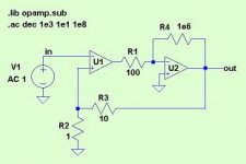
If you are interested, there is another way to do what I think you are trying to do. See conceptual circuit below. Might be simpler to implement and will be very stable. That is to use a wide-band differentiator (U1) feeding an op-amp (U2). Varying R4 will vary the feedback factor without changing the GBP. U1 can be a transconductance amp too, or a discrete subtractor like you have in your current design. U1 needs to have a GBP greater than U2.
I would have thought a couple of decent, off the shelf amps would do.
I would have thought a couple of decent, off the shelf amps would do.
Attachments
- Status
- This old topic is closed. If you want to reopen this topic, contact a moderator using the "Report Post" button.
- Home
- Amplifiers
- Solid State
- Gain Blockwith Variable Loop Gain