Hey everyone, this is my first post.
I may not be an expert at audio, but Im learning, just keep in mind what you are about to read will make you wonder how stupid I am.
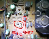
A needle fell through the top of the NAD 3130's case and bridged VR401 with Q407's E contact.
After this, I think the variable resistor caught fire, because I could smell smoke. So now it doesn't work at all, well, it turns on, but all I get is static and audible hiss.
Im clueless as to what to do for lack of knowledge of what parts to buy.
I can solder the new parts to the board etc and do necessary repairs...
I was just hoping someone could push me in the right direction.
Attached is a picture showing what I see, (And some obvious blackening from the short circuiting of VR401 and Q407's E contact), just for reference purposes.
Again, I cannot stress how stupid I already feel, Im just looking for a solution.
Thanks in advance for any help.
Alex
I may not be an expert at audio, but Im learning, just keep in mind what you are about to read will make you wonder how stupid I am.
A needle fell through the top of the NAD 3130's case and bridged VR401 with Q407's E contact.
After this, I think the variable resistor caught fire, because I could smell smoke. So now it doesn't work at all, well, it turns on, but all I get is static and audible hiss.
Im clueless as to what to do for lack of knowledge of what parts to buy.
I can solder the new parts to the board etc and do necessary repairs...
I was just hoping someone could push me in the right direction.
Attached is a picture showing what I see, (And some obvious blackening from the short circuiting of VR401 and Q407's E contact), just for reference purposes.
Again, I cannot stress how stupid I already feel, Im just looking for a solution.
Thanks in advance for any help.
Alex
Attachments
Kar, I have enough confidence that its fixable, but when you say post a circuit, are you asking for the whole diagram? Im hoping theres someone on here with the same AMP as me to tell me which parts exactly I've damaged, because, while theres visible damage to the variable resistor, I don't have confidence that replacing just that will make it work as good as new.
Infact, I've bought the replacement variable resistor, and put it back in, and Im still getting some very unstable output. Like I said, I need someone who has experience with this amp 'intimately' so to speak. Any help will not go un-noticed.
Alex
Infact, I've bought the replacement variable resistor, and put it back in, and Im still getting some very unstable output. Like I said, I need someone who has experience with this amp 'intimately' so to speak. Any help will not go un-noticed.
Alex
It is extremely rare to just replace visably faulty components and have things work perfectly as before, please bear this in mind, ill try to give you some advise but you would normally need a few essential items of equipment before attempting a fix.
firstly see if your output transistors are dead, do this by connecting a multimeter to your speaker outputs on the faulty channel if your measuring around 30volts, which is around the rail voltage then the transistors are toast! if you are reading millivolts idealy under 30mv then the problem lies with the damaged components (doh!) and very probably the drivers (the squarer looking transistors. please post your findings so further help my come.
also a word of advise if you havn't got a meter or dont know how to use one, i would suggest you find someone who is qualified in such things to have a look
Agree with most of the comments so far. You can use a 60 watt in series with the mains to limit any further damage.
A lot depends on your experience, if you were handed a bag of unmarked transistors some faulty (leaky junctions, O/C junctions S/C junctions etc) and some perfect could YOU reliably and confidently say which were good or bad and even identify their polarity .
Sorry to sound a bit harsh but it's not as simple as saying that such and such a part will be faulty -- replace it and all will be well.
If you replace the bias pot do you know how to adjust it, whether to have it on min or max resistance to begin with etc.
If you can come up with a circuit of the output stage I am sure you can fix it.
You have to remember how the fault occured, you may have zapped even the input stage as well-- you need a game plan to fix it.
Regards Karl
Mooly said:Agree with most of the comments so far. You can use a 60 watt in series with the mains to limit any further damage.
A lot depends on your experience, if you were handed a bag of unmarked transistors some faulty (leaky junctions, O/C junctions S/C junctions etc) and some perfect could YOU reliably and confidently say which were good or bad and even identify their polarity .
Sorry to sound a bit harsh but it's not as simple as saying that such and such a part will be faulty -- replace it and all will be well.
If you replace the bias pot do you know how to adjust it, whether to have it on min or max resistance to begin with etc.
If you can come up with a circuit of the output stage I am sure you can fix it.
You have to remember how the fault occured, you may have zapped even the input stage as well-- you need a game plan to fix it.
Regards Karl
Personally I would remove the output transistors and link the output back into the LTP. Only once had I got the driver working and set the bias to minimum would I even consider refitting output transistors (after checking they are not faulty !)
Even then I sometimes only fit one pair of output transistors to reduce costs if they should still blow.
Costs is one reason I go for cheapo nasty MOSFETS IRFP240/9240.
At £2 each on ebay they are almost peanuts.
I also always put a zener across the bias cct to ensure it cant go way out of bounds. On a MOSFET amp I put in a 7 volt zener and the MOSFETs wont blow at that voltage.
"Even then I sometimes only fit one pair of output transistors to reduce costs if they should still blow."
Good advice on a larger amplifier, this one only has one pair.
"Costs is one reason I go for cheapo nasty MOSFETS IRFP240/9240.
At £2 each on ebay they are almost peanuts."
Would require a re-design of the bias circuit, reduce amplifier output power, and cost too much (3055/2955 can be had for about USD$1 each).
"I also always put a zener across the bias cct to ensure it cant go way out of bounds. On a MOSFET amp I put in a 7 volt zener and the MOSFETs wont blow at that voltage."
That may work on lateral FETs, but not on the IRF types you suggested.
http://www.vishay.com/docs/90274/90274irf.pdf
According to the data, a 7V zener will hold it down to about 20A.
djk said:"Even then I sometimes only fit one pair of output transistors to reduce costs if they should still blow."
Good advice on a larger amplifier, this one only has one pair.
"Costs is one reason I go for cheapo nasty MOSFETS IRFP240/9240.
At £2 each on ebay they are almost peanuts."
Would require a re-design of the bias circuit, reduce amplifier output power, and cost too much (3055/2955 can be had for about USD$1 each).
"I also always put a zener across the bias cct to ensure it cant go way out of bounds. On a MOSFET amp I put in a 7 volt zener and the MOSFETs wont blow at that voltage."
That may work on lateral FETs, but not on the IRF types you suggested.
http://www.vishay.com/docs/90274/90274irf.pdf
According to the data, a 7V zener will hold it down to about 20A.
Not in my experience !
I have opened up the pot until I got 6.9 volts on it and get 25mA bias current per MOSFET on average. I have opened the bias pot right up until the zener kicked in and it was still barely more than 30mA.
Because I used multiple sets of output transistors the bias through each MOSFET does vary a bit due to each having slightly different turn on voltages.
The datasheet says 3 to 4 volts to switch on so my 3.5 volts per MOSFET sound sabout right.
I use 0R22 output resistors so even at 4 volts you are only pulling 2.3 amps.
Thank you for all your help so far.
Wow, I guess Im really unprepared.
Jaycee: How would I identify all the transistors in VR401's path?
First off, I've made some progress, I bought a replacement 50KOhm variable resistor to bridge the points left by the faulty one. Im sure that the input stage is fine because Im still getting audio output, the only problem is that it is very unstable, and when switching on "Low Level" or "Bass EQ", my speakers pop out, and I wouldn't like to keep testing these Sonab B52's until they REALLY blow out.
Next up, I've been doing some research, and in some cases, people have mentioned "high voltages almost certainly cook your boards electrolytic capacitors".
If so, would this mean I would have to replace all the capacitors, because I would be more than happy to if it would refurbish the board to a certain extent.
Finally, the resistors etc, would any of these be blown? Diode's?
Also my Amp makes use of Motorola MJ2955 transistors, 4 of them to be exact (Assuming two for each channel?)
Would these be the transistors that you all suspect to have been blown in the process of this short circuit?
Thank you all for your help so far!!!
Alex
Alex,
You need to come up with a circuit !! If you do that you stand a much better chance of fixing it. The questions you are asking show you need guiding through it. Post a new thread to see if anyone has one") The output transistors usually fail short circuit collector to emmiter-- have you measured them. Is the other channel 100% ok. Forget caps for now. Get a circuit.
The output transistors usually fail short circuit collector to emmiter-- have you measured them. Is the other channel 100% ok. Forget caps for now. Get a circuit.
You need to come up with a circuit !! If you do that you stand a much better chance of fixing it. The questions you are asking show you need guiding through it. Post a new thread to see if anyone has one
The output transistors usually fail short circuit collector to emmiter-- have you measured them. Is the other channel 100% ok. Forget caps for now. Get a circuit.Mooly said:Alex,
You need to come up with a circuit !! If you do that you stand a much better chance of fixing it. The questions you are asking show you need guiding through it. Post a new thread to see if anyone has one
Im very unsure as to what your asking me...
Do you want a circuit diagram?
Alex
Hi Alex,
I don't want a circuit you do. If you can post a circuit here I am sure you can be "talked" through what to do to fix it.
If the unit were on my bench it's easy, at the end of a keyboard I need to see exactly whats what. Have a search on the Web -- there must be one out there.
Regards Karl
I don't want a circuit
you do. If you can post a circuit here I am sure you can be "talked" through what to do to fix it.If the unit were on my bench it's easy, at the end of a keyboard I need to see exactly whats what. Have a search on the Web -- there must be one out there.
Regards Karl
Rechecked my help ticket at NAD Electronics today, no luck.
The only transistors that I think my board has are the Motorola MJ2955's.
If so, replacements need to be ORDERED overseas and shipped.
Im just a kid, not some adult with a credit card, so this will be a very VERY tricky repair, and my very first at that.
The only transistors that I think my board has are the Motorola MJ2955's.
If so, replacements need to be ORDERED overseas and shipped.
Im just a kid, not some adult with a credit card, so this will be a very VERY tricky repair, and my very first at that.
both channels are near unresponsive and unclear, minimal sound is audible, which led me to believe that this single bias controller (when shorted with the Q407) was something the whole board utilizes.
Lets just say, I do NOT want to buy a new amp for the sake of using my speakers, and until then, Im on Integrated laptop speakers and Sennheiser PXC 250 headphones.
In short, Im fixing it no matter what.
What kind of tests are these?
EDIT: Yes, I have a source of parts, but the MJ2955 will be tricky for me to get if the component is damaged.
Hi Alex --- This sounds like a real challenge !
More questions,
1. Do you have a meter (D.V.M.)
2. Can you solder neatly.
3. Can you unsolder neatly ( using braid )- thats just as important.
4. Have you any experience with electronics at all, for example, would you be able to identify an N.P.N. transistor from a P.N.P. just by measuring it or are we starting right at the beginning. Which is fine
Any chance if poss of a picture of the insides of the amp, not vital though.
Mooly said:Hi Alex --- This sounds like a real challenge !
More questions,
1. Do you have a meter (D.V.M.)
2. Can you solder neatly.
3. Can you unsolder neatly ( using braid )- thats just as important.
4. Have you any experience with electronics at all, for example, would you be able to identify an N.P.N. transistor from a P.N.P. just by measuring it or are we starting right at the beginning. Which is fine
Any chance if poss of a picture of the insides of the amp, not vital though.
I'm working on the D.V.M as I already know its essential, should get one soon, I can solder, thats about all I can say for myself, unsoldering, what do you mean by braid?
My experience in board electronics is limited to a very advanced field, processors, nano-technology, ASIC chips (when I mention all these, Im referring to their inner workings, my experience in application is limited)
As for identifying parts, I'd be pretty basic, but give me a 333MHz MIPS processor and I could probably use it to hack into a Russian Air Force Base, which isn't exactly useful for repairing an amp so forget that part.
I guess, yeah, I would be starting from the very beginning but don't underestimate me much, I have the capacity for knowledge, and a great capacity at that.
Hold out on the picture, Im currently with a very useless cellphone camera, I will borrow something highres and get some detailed photos.
EDIT: Sorry, didn't know certain words were banned.
- Status
- This old topic is closed. If you want to reopen this topic, contact a moderator using the "Report Post" button.
- Home
- Amplifiers
- Solid State
- Problem with a NAD 3130