Hello,
Everything is in the subject: i try to build a low frequencies preamplifier with a differential structure (40dB, input voltage swing: from 0.01V to 0.1V and a good THD over the entire bandwith(audio)).
I simulate my circuits in ORCAD Pspice.
With a simple diff pair with current sink followed by a class A amplifier DC coulped with the previous stage (for the feedback) i can't lower the thd specialy when the input voltage rise and i would like to get a good thd over the dynamic of the signal.
When Vce swing Ic swing too so béta swing too=>distortion,
I heard somewhere that cascode could minimize the third order distortion is that right?, is there any other solution?
I also heard about cross coupled amplifier...
If somebody can bring some theory about linearisation of the bjt diff amp...
Sincerely,
dd
dododio said:Hello,
When Vce swing Ic swing too so béta swing too=>distortion,
dd
Hwo about using a constant current source to keep the current the same ?
Do not inject, do not plug signal bigger than the transistor bias
and adjust your impedance using dummy resistances into the input as loads to match your pré amplifier...keep the signal inside the limits and distortion will be something you will not even listen.
Of course measurements instruments will see distortions and will read them..... but you will not perceive...so... not your problem...the problem belongs to the Measurement instrument...it may be disturbed or bothered...you will remain very happy listening good sound.
Big secret... and for free... adjust your non distorted level to 75 percent of your volume.... you will have room to increase low level from your audio source and will not have too much risk operating confortable audition levels.
Distortions will always exists....and do not bother about the amplifiers...the speaker will be distorting 100 percent more than the amplifiers...so.... the amplifier is something that is not the real problem to create worries.
Watch the speaker, that dam thing...the air pump... awfull mechanics... very ancient thing.... the guilty is there!
Give a shot into your 6 volts RMS output pré amplifier...not needed, problem creator... the audio sources already has level enougth to drive any power amplifier to the maximum level of power..so....pré amplifiers is one more thing to create problems, as it is inside the audio chain...use potenciometers to control the input volume and be happy my friend.
regards,
Carlos
Re: Do not inject, do not plug signal bigger than the transistor bias
People spend ages getting the amp right then send the signal to a speaker with a wildy fluctuating frequency curve.
destroyer X said:
Watch the speaker, that dam thing...the air pump... awfull mechanics... very ancient thing.... the guilty is there!
regards,
Carlos
People spend ages getting the amp right then send the signal to a speaker with a wildy fluctuating frequency curve.
Re: Re: Do not inject, do not plug signal bigger than the transistor bias
Looks like to don't visit the loudspeaker forum often enough...
nigelwright7557 said:
People spend ages getting the amp right then send the signal to a speaker with a wildy fluctuating frequency curve.
Looks like to don't visit the loudspeaker forum often enough...
Re: Re: Re: Do not inject, do not plug signal bigger than the transistor bias
Not at all, I just read the loudspeaker specification pdf's !!!
ttan98 said:
Looks like to don't visit the loudspeaker forum often enough...
Not at all, I just read the loudspeaker specification pdf's !!!
dododio said:Hello,
- low frequencies preamplifier
- with a differential structure
- (40dB,
- input voltage swing: from 0.01V to 0.1V and
- a good THD over the entire bandwith(audio)).
I simulate my circuits in ORCAD Pspice.
- a simple diff pair with
- current sink
- followed by a class A amplifier DC coulped with the previous stage (for the feedback)
i can't lower the thd specialy when the input voltage rise and i would like to get a good thd over the dynamic of the signal.
When Vce swing Ic swing too so béta swing too=>distortion,
I heard somewhere that cascode could minimize the third order distortion is that right?, is there any other solution?
I also heard about cross coupled amplifier...
If somebody can bring some theory about linearisation of the bjt diff amp...
Sincerely,
dd
When I know too little, I do not want to join in doing speculations.
I have several questions, for clarification, if you can not post a Drawing / Schematic,
to let us see what is going on.
------------------------
1. Power supply? Voltage?
I suppose dual, negative + postive with 0 Volt in middle.
2. 40 dB .. what?
If you by this mean x100 v-gain, maybe
3. LOAD?
What kind of load you intend to drive with preamp?
1 kohm .. or at worst case 5 or 10 kohm
4. What output max voltage you need across this load?
Using 0.01 Vrms / 0.1 Vrms .. at gain x100 = 1 - 10 Vrms Output!!!
This means a peak voltage out = 1.414 x 10 = +- 14.14 Volt.
Would require, in my book, at least a +- 20 Volt supply.
Preferably, a well regulated supply.
This is what good preamplifier deserves.
5. Not many devices fed from a preamp need more than 1- 2 Vrms input.
As hinted by destroyer X, already.
----------------------
I look forward to get mor info.
Then I would give you some good advices, how to do.
And how to lower your THD a bit. For good audio sound ( maybe even Hi-Fi
") ).
).As the others posters here have good knowledge to advice, as well.
Regards, Lineup
Re: Re: How to get the less distortion with BJT?
And how I am supposed to learn if I dont join in and ask questions !!!!!
I have been in electronics for 32 years so I hardly a novice !
You need to take a long hard look at a speaker datasheet before having a dig at me.
The Fane Collossus has more curves than Pamela Anderson !!!
lineup said:
When I know too little, I do not want to join in doing speculations.
Regards, Lineup
And how I am supposed to learn if I dont join in and ask questions !!!!!
I have been in electronics for 32 years so I hardly a novice !
You need to take a long hard look at a speaker datasheet before having a dig at me.
The Fane Collossus has more curves than Pamela Anderson !!!
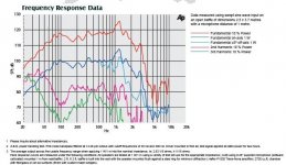
Attachments
Hi Guys
I think what dododio is looking for is somewhat more technical. The crosscoupled design he mentions does work to a certain extent but has its drawbacks there is a thread about it here on the forum and you could search for it. Cascoding does help to a degree as does the use of cfp.
Dododio if you really want to get into it i can help you on the way, but im a terrible teacher and i dont have much time so youll have to read up on it by yourself. So I suggest you to look up the patents by Patric Quin 4,146,844 and the later improved versions by James Woo 4,779,057. Strangely enough there is only one person that has incorperated these techniques in a amp and i can bet that amp sounds damm fine. Perfect for preamps. I think there be some stability issues but theres a solution to every problem. If you have problems getting this info drop me a email and ill send it to you. I havent got the time to try or look into it with care, my wife will kill me and my hobbies .
.
Alex
I think what dododio is looking for is somewhat more technical. The crosscoupled design he mentions does work to a certain extent but has its drawbacks there is a thread about it here on the forum and you could search for it. Cascoding does help to a degree as does the use of cfp.
Dododio if you really want to get into it i can help you on the way, but im a terrible teacher and i dont have much time so youll have to read up on it by yourself. So I suggest you to look up the patents by Patric Quin 4,146,844 and the later improved versions by James Woo 4,779,057. Strangely enough there is only one person that has incorperated these techniques in a amp and i can bet that amp sounds damm fine. Perfect for preamps. I think there be some stability issues but theres a solution to every problem. If you have problems getting this info drop me a email and ill send it to you. I havent got the time to try or look into it with care, my wife will kill me and my hobbies
. Alex
The following texts of french emanation about very linear bipolar input stages are classical now :
http://peufeu.free.fr/audio/memory/patents/lavardin-inputstage.zip
http://peufeu.free.fr/audio/memory/
In his series in "L'Audiophile", Perrot measured far lower distorsion from his input stage than from those of Tektronix (called "Cascomp").
http://peufeu.free.fr/audio/memory/patents/lavardin-inputstage.zip
http://peufeu.free.fr/audio/memory/
In his series in "L'Audiophile", Perrot measured far lower distorsion from his input stage than from those of Tektronix (called "Cascomp").
Hi Forr
Who is textronix?? Ones using Woo inventions??
I have read the sites you mentioned. It is good yes and i thought of mentioning it as it is simple and effective. Ive used and seen cfp cascoded designs even before i was aware of perrot. We did experiments at varsity concerning linearity and this type of design our professor showed us. Never looked at it from a memory effect perspective but from a linearity one, i was in varsity a long time ago, before perrots patent. The two go hand in hand as i see it.
A shootout would be interesting between the two. There is also now a third very clever and simple design by i think his name is kullish, using error correction that can be brought into the mix. Someone that comes to this forum has designed a circuit based on woo s ideas that looks like it will outperform woo s original and this person i am pretty sure knows the perrot papers. I am not so sure perrots circuit would come out on top, this offcourse is from a THD perspective as there are other matters too especially in audio. The only one i have listened to is perrots circuit.
Alex
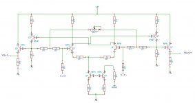
you don't seem to have any global feedback, which is really important with a diff amp. another possible problem is your "current source" which looks like it's operating more like an "amplified" resistor. a better approach would be to dump the "mirror" transistor in the current source and replace it with a pair of diodes. the way a current source works is that it sets up a reference voltage at the base of the CS transistor, usually with a pair of diodes or an LED. the transistor tries to maintain one diode drop across the B-E junction, while dropping the other diode drop across the emitter resistor. the voltage across the emitter resistor reduces the B-E current until it stabilizes at a preset current, and the current source is in equalibrium. any attempts to change that current (such as changing the voltage on the collector) will cause the transistor to maintain equalibrium, which keeps the current constant.
Attachments
Hi,
forr, thank for your links,
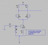
unclejed 613, i forget to connect the B&C for the current mirror and there is a negative global feedback formed by resistor after class a common emiter stages.
Another question is : if the transistor is current feed then the distortion comming from Ib(Vbe)(with the exponnential relationship) will be cancelled? => if this is right this kind of attack could support a greater voltage input swing than a classical voltage attack (so with less distortion)?
So there is 2 kind of distortion (dependant on amplitude)?
sincerely,
ch
forr, thank for your links,
unclejed 613, i forget to connect the B&C for the current mirror and there is a negative global feedback formed by resistor after class a common emiter stages.
Another question is : if the transistor is current feed then the distortion comming from Ib(Vbe)(with the exponnential relationship) will be cancelled? => if this is right this kind of attack could support a greater voltage input swing than a classical voltage attack (so with less distortion)?
So there is 2 kind of distortion (dependant on amplitude)?
sincerely,
ch
homemodder said:Hi Forr
Who is textronix?? Ones using Woo inventions??
I have read the sites you mentioned. It is good yes and i thought of mentioning it as it is simple and effective. Ive used and seen cfp cascoded designs even before i was aware of perrot. We did experiments at varsity concerning linearity and this type of design our professor showed us. Never looked at it from a memory effect perspective but from a linearity one, i was in varsity a long time ago, before perrots patent. The two go hand in hand as i see it.
A shootout would be interesting between the two. There is also now a third very clever and simple design by i think his name is kullish, using error correction that can be brought into the mix. Someone that comes to this forum has designed a circuit based on woo s ideas that looks like it will outperform woo s original and this person i am pretty sure knows the perrot papers. I am not so sure perrots circuit would come out on top, this offcourse is from a THD perspective as there are other matters too especially in audio. The only one i have listened to is perrots circuit.
Alex
Hi Homemolder
Tektronix is a famous maker of osccilloscopes.
Perrot measured many other kinds of differential input stages, many were better than the Cascomp. I can provide you details, just email me (in french but figures are easy to understand).
Perrot prefered circuit should not be seen as a variation of the Sziklai pair neither as using a cascode stage. Its input bipolar is loaded by a CCS and is followed by a complementary PNP - NPN with coupled emitters which is a series differential stage, also called a Rush circuit. A common base transistor does not mean that a circuit is necessarily a cascode.
- Status
- This old topic is closed. If you want to reopen this topic, contact a moderator using the "Report Post" button.
- Home
- Amplifiers
- Solid State
- How to get the less distortion with BJT?