Hi,
I would like to test the MOSFET amplifier designed by M. Renardson, from
http://www.angelfire.com/ab3/mjramp/amp7.html.
http://www.angelfire.com/ab3/mjramp/construct.html
http://www.angelfire.com/ab3/mjramp/simple5.html
Did anybody experiment with it? How does it sound?
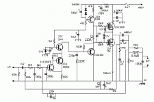
I would like to ask some advice regarding the implications of increasing the voltage from 60V to 90V and eventually adding a second pair of MOSFETS for extra output power.
Besides choosing capacitors of higher voltage for the power supply and for the 4700uF output (100V instead of 63V), do we also need to increase the output capacitor from 4700uF to 6800uf or higher in order to accomodate the extra power?
If we increase the value of the output capacitor, since it is part of the feedback loop, do we also need to adjust the values of any other components ?
Do we need to increase the value of the power supply capacitors from 12000uf to let say 20000uf?
To add a second pair of MOSFETS, I assume that I would need to add another pair of resistors (330R) and 12V zener diodes to drive these MOSFETS. Is this correct?
Any other advice is welcome")
Thanks!
I would like to test the MOSFET amplifier designed by M. Renardson, from
http://www.angelfire.com/ab3/mjramp/amp7.html.
http://www.angelfire.com/ab3/mjramp/construct.html
http://www.angelfire.com/ab3/mjramp/simple5.html
Did anybody experiment with it? How does it sound?
I would like to ask some advice regarding the implications of increasing the voltage from 60V to 90V and eventually adding a second pair of MOSFETS for extra output power.
Besides choosing capacitors of higher voltage for the power supply and for the 4700uF output (100V instead of 63V), do we also need to increase the output capacitor from 4700uF to 6800uf or higher in order to accomodate the extra power?
If we increase the value of the output capacitor, since it is part of the feedback loop, do we also need to adjust the values of any other components ?
Do we need to increase the value of the power supply capacitors from 12000uf to let say 20000uf?
To add a second pair of MOSFETS, I assume that I would need to add another pair of resistors (330R) and 12V zener diodes to drive these MOSFETS. Is this correct?
Any other advice is welcome
Thanks!
Attachments
Hi,
As a huge fan of Lateral FET's I have to add my two penneth
Easy bits first, yes just add an extra pair of 330 ohms and parallel the outputs. You could always use double die MOSFET's instead such as BUZ900D and BUZ905D (TO3 Package). The 12 volt zeners, it's not usual to use back to back zeners, normally just a zener and series In4148 if you want to include them at all !! I normally do not.
The value of the output cap is unrelated to power output.
I imagine it sounds -- well -- very nice
Any reason why this particular design ?
Regards Karl
Hi Karl,
Thank you for your feedback.
I looked at this design because of its simplicity, yet very low noise/distortions and good linearity.
I would like to build a multi-channel home theater amplifier, and eventually pair it with one of these speakers: the Gallo reference speakers (http://www.roundsound.com/reference-speakers.htm) or the Druid MK4 (http://www.zuaudio.com/druid_2.asp).
I think that increasing the voltage I may be able to get at least 80W of power, which should be enough. Maybe I would need a more powerful amplifier for powering the woofers' second second coil of the Gallo speakers.
What do you think about a design that uses symetrical voltage? Could we get similar performances using only 7 transistors? Such a design may have an advantage that the capacitors will need lower voltage, and I could also get more power, especially for the woofer speakers.
Regards,
Alexandru
Hi Karl,
There is something more... I looked again at the schematics, and the zeners are after the 330 ohms resitors, which makes it more difficult to add another pair of transistors, if we keep the zeners. Therefore your idea to use the BUZ900D and BUZ905D MOSFETS would be better.
Do you know where to buy a matched pair of BUZ900D and BUZ905D?
Thanks,
Alexandru
tryalx said:Hi,
I would like to test the MOSFET amplifier designed by M. Renardson, from
http://www.angelfire.com/ab3/mjramp/amp7.html.
http://www.angelfire.com/ab3/mjramp/construct.html
http://www.angelfire.com/ab3/mjramp/simple5.html
--------------
Any other advice is welcome
A general comment on Mike J. Renardson.
The guy obviously knows a lot about amplifier designs.
As a matter of facts, I was browsing his website a couple of weeks ago
and downloaded some of his best stuff .......
I would say his later amplifiers, like MJR-6, MJR-7 are 'his best'.
( Because usually people progress, no matter from which starting level )
He has got a lot of interesting knowledge Articles, besides amp projects:
DESIGNING AUDIO POWER AMPLIFIERS
http://www.angelfire.com/ab3/mjramp/designing.html
# EFFECT OF FEEDBACK ON HARMONICS. Updated 13-May-2006.
It is well known that a square-law amplifier adds only second harmonics with no feedback, but many high order harmonics with feedback applied, but this is almost entirely misleading, as explained here.
# INPUT STAGE DISTORTION.
Seven of the most common one and two transistor input stages are compared by calculating their levels of intermodulation distortion under identical stage output current levels.
# SLEW RATE AND T.I.D. (Updated 12 June 2006)
The maximum slew rate requirement and the design techniques for low t.i.d. are investigated. Now includes measurement results for maximum CD slew rate.
# MEASURING DISTORTION.
To test our low distortion designs an alternative to buying expensive distortion measuring instruments is to use the bridge-nulling method in which the input and output are directly compared.
# PHASE INTERMODULATION.
# Explanation, reduction and measurement of phase intermodulation distortion.
# COMMON-MODE DISTORTION.
Common-mode distortion is examined, a test method described, and the performance of typical input stage transistors tested and compared.
# MEASURING CAPACITOR DISTORTION. (Updated 22-Apr-2006)
Capacitors are known to add a little low order harmonic distortion, but does transient testing reveal something a lot worse than this?
# ERROR FEEDBACK AND NESTED LOOPS.
An examination of how effective these methods can be compared to overall negative feedback.
# SYMMETRY. (Updated 01-May-2006)
Symmetry can be good or bad, but just aiming for maximum circuit symmetry may add unnecessary complexity with no real benefit. It is possible in principle to achieve zero distortion in some circuits with correct use of symmetry.
DISTORTION - HOW LOW CAN YOU GO?
Is there any limit to how far power amplifier distortion can be reduced?
The startpage of his website, with amplifier project and articles
is:
http://www.angelfire.com/ab3/mjramp/index.html
Regars Lineup
tryalx said:Hi,
I would like to test the MOSFET amplifier designed by M. Renardson, from
http://www.angelfire.com/ab3/mjramp/amp7.html.
http://www.angelfire.com/ab3/mjramp/construct.html
http://www.angelfire.com/ab3/mjramp/simple5.html
Any other advice is welcome
Thanks!
Looks very similar to an old Maplin 75WRMS amplifier.
There seems to be quite a few more components than is absolutely necesary in this design. Typical of a designer who has been around a while !
I prefer to stick to simple designs. I dont use zeners on the MOSFET gates. I lose the output inductor. I keep the zobel network tho. I would only use one low pass filter on the input.
I probably wouldnt use the 1000uF on the output stage.
Implication 60V to 90V
Now that's a drastic change. You would at least need to check the biasing and check the SOAR of all transistors. I don't have the time at the moment to have a more closer look to the schematic, but from experience I doubt that you can increase rail voltage by that amount without reworking the circuit a bit.
Have fun, Hannes
Hi Mooly,
I have read through your "My MOSFET Amplifier designed for music" topic, and there was a lot of excitement around.
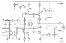
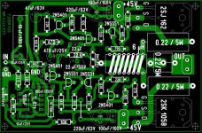
There were several comments and possibly some changes in the original design and board layout. Can you please post the latest schematic and PCB layout?
You have also given a lot of information about measurements and components types. Do you have any website with all these details summarized? Otherwise, would it be possible to have the final conclusions compacted in one post? This would be very helpful!
Thank you also for the link for the components!
Cheers,
Alexandru
I have read through your "My MOSFET Amplifier designed for music" topic, and there was a lot of excitement around.
There were several comments and possibly some changes in the original design and board layout. Can you please post the latest schematic and PCB layout?
You have also given a lot of information about measurements and components types. Do you have any website with all these details summarized? Otherwise, would it be possible to have the final conclusions compacted in one post? This would be very helpful!
Thank you also for the link for the components!
Cheers,
Alexandru
Hi,
Sorry for not replying sooner --- for some reason not notified of new posts on this thread -- Gremlins
The circuit is unchanged component wise apart from a 10 ohm 2 watt resistor across the output inductor. I kept missing it off the CAD program when I copied it over from the hand drawn originals.
Alex looks to have done a fantastic job with the PCB layout. I have "visually" checked it over and it looks fine. As you will have gathered the originals were very much a one off.
A website I have only had a PC at home for 18 months or so. It was hard enough figuring out how to send an E-Mail.
Final conclusions, thats easy,
BUILD IT. LISTEN TO IT. REDISCOVER YOUR MUSIC COLLECTION.
This amp does truly sound wonderful, you can close your eyes and be transported away with the music. You will find you are not listening to the amp, the music shines through. And that is the problem for me in that I wonder now how to improve on it subjectively, after 4.5 years it still has all the magic, nothing I have heard has made me want to change it.
If you do intend building it I can give any advice etc via this forum.
Regards Karl
Sorry for not replying sooner --- for some reason not notified of new posts on this thread -- Gremlins
The circuit is unchanged component wise apart from a 10 ohm 2 watt resistor across the output inductor. I kept missing it off the CAD program when I copied it over from the hand drawn originals.
Alex looks to have done a fantastic job with the PCB layout. I have "visually" checked it over and it looks fine. As you will have gathered the originals were very much a one off.
A website
I have only had a PC at home for 18 months or so. It was hard enough figuring out how to send an E-Mail. Final conclusions, thats easy,
BUILD IT. LISTEN TO IT. REDISCOVER YOUR MUSIC COLLECTION.
This amp does truly sound wonderful, you can close your eyes and be transported away with the music. You will find you are not listening to the amp, the music shines through. And that is the problem for me in that I wonder now how to improve on it subjectively, after 4.5 years it still has all the magic, nothing I have heard has made me want to change it.
If you do intend building it I can give any advice etc via this forum.
Regards Karl
Hi Hannes,
Thank you for your feedback, it is a good point. So I guess, first I will build the amplifier as stated on the schema and messure the B-E voltages of the transistors. The transistors will handle a 90-100 volt rail voltage. After I increase the voltage (maybe in steps) I will messure these voltages and if needed adjust the values of the resistors. I am not sure whether this is the right way of doing it, but I can try
Regards Alexandru
tryalx said:Hi Hannes,
Thank you for your feedback, it is a good point. So I guess, first I will build the amplifier as stated on the schema and messure the B-E voltages of the transistors. The transistors will handle a 90-100 volt rail voltage. After I increase the voltage (maybe in steps) I will messure these voltages and if needed adjust the values of the resistors. I am not sure whether this is the right way of doing it, but I can try
Regards Alexandru
The ratios of the resistors will stay the same so you might not need to adjust any.
Just watch the pwoer rating of the resistors at higher voltages.
Check the transistors in the driver stage are correctly rated for higher voltage.
Hi Karl, everybody,
I am not sure I have understood correctly. Are you mentioning that the resistor R25 which is a 10 ohm should be 2Watt, or is there another resistor missing from the schema?
So apparently there are at least two schemas that are intriguing, which is yours and also the MJR-7 of Mike Renardson. I may also try another one from AmpsLab: http://www.ampslab.com/lm60.htm or http://www.ampslab.com/lm60_schematics.htm
Before ordering the components, my I ask you a question about your choise of transistors. The schema contains 2N5401 and 2N5551, instead of BCxxx or BDxxx series (BC549 or BD139, BD140) transistors, or 2SCxxxx or 2SAxxxx series (2SC2547E, 2SC2911, 2SA1209) transistors found in the MJR-7 schema. Do the 2Nxxxx transistors have better audio properties?
If I will use two of the final MOSFETS in paralel or a BUZ900D/BUZ905D or equivalent, for more power into 4 ohm do we need to replace the transistors Q6 and Q7 with a medium power version? Which transistors should we use in that case for Q6 and Q7?
Do you have any suggestions on what type of capacitors to use, ceramic, mica, polyester, polypropylene? Which one did you use?
Yet another question, maybe for everybody: do we need to pair any of the transistors? I assume that using transistors in pairs with similar gains would improve the sound, wouldn't it?
Does anybody has a simple circuit that I could use to pair the transistors (Biploar an MOSFETS) by measuring the gain (output/input)?
Is there any website where we can buy paired transistors?
Thanks, Alexandru
The circuit is unchanged component wise apart from a 10 ohm 2 watt resistor across the output inductor. I kept missing it off the CAD program when I copied it over from the hand drawn originals.
I am not sure I have understood correctly. Are you mentioning that the resistor R25 which is a 10 ohm should be 2Watt, or is there another resistor missing from the schema?
So apparently there are at least two schemas that are intriguing, which is yours and also the MJR-7 of Mike Renardson. I may also try another one from AmpsLab: http://www.ampslab.com/lm60.htm or http://www.ampslab.com/lm60_schematics.htm
Before ordering the components, my I ask you a question about your choise of transistors. The schema contains 2N5401 and 2N5551, instead of BCxxx or BDxxx series (BC549 or BD139, BD140) transistors, or 2SCxxxx or 2SAxxxx series (2SC2547E, 2SC2911, 2SA1209) transistors found in the MJR-7 schema. Do the 2Nxxxx transistors have better audio properties?
If I will use two of the final MOSFETS in paralel or a BUZ900D/BUZ905D or equivalent, for more power into 4 ohm do we need to replace the transistors Q6 and Q7 with a medium power version? Which transistors should we use in that case for Q6 and Q7?
Do you have any suggestions on what type of capacitors to use, ceramic, mica, polyester, polypropylene? Which one did you use?
Yet another question, maybe for everybody: do we need to pair any of the transistors? I assume that using transistors in pairs with similar gains would improve the sound, wouldn't it?
Does anybody has a simple circuit that I could use to pair the transistors (Biploar an MOSFETS) by measuring the gain (output/input)?
Is there any website where we can buy paired transistors?
Thanks, Alexandru
Attachments

The ratios of the resistors will stay the same so you might not need to adjust any.
Just watch the pwoer rating of the resistors at higher voltages.
Check the transistors in the driver stage are correctly rated for higher voltage.
Thank you for your feedback I appreciate all the input I get.
Regards, Alexandru
Smooting capacitors PSU
I have noticed two trends regarding the smoothing capacitors from the power supply:
1. Use several lower value (e.g. 1000uf or 2200uf) in parallel to yield the desired capacity and current, let's say (10000-20000uf)
2. Use one or two of 6700uf with very high ripple effect for each +- rail.
Using one/two capacitors allows to build a more compact PSU, but what about filtering and hummm noise?
From experience what is the best approach? What is the trend in professional audio equipment?
Thanks, Alexandru
Mooly said:I saw you were online. I haven't figured out how to link to other threads -- it never works for me !!!
Look in the solid state forum, it's called "My MOSFET Amplifier designed for music". Have a read
A website
Final conclusions, thats easy,
BUILD IT. LISTEN TO IT. REDISCOVER YOUR MUSIC COLLECTION.
This amp does truly sound wonderful, you can close your eyes and be transported away with the music. You will find you are not listening to the amp, the music shines through. And that is the problem for me in that I wonder now how to improve on it subjectively, after 4.5 years it still has all the magic, nothing I have heard has made me want to change it.
If you do intend building it I can give any advice etc via this forum.
Regards Karl
Mooly, my diyaudio fellow friend, somewhere in this world.'
I have followed The thread with your MOSFET amplifier
(only posted one post, about GATE Resistor values, compared to Nelson Pass ).
I think your amplifer deserves a bit more attention.
And this is what you want to share with us.
I will put your topic alive again.
Because several diyaudio builders may discover something Very Good.
Mooly: My MOSFET amplifier designed for music
Lineup - your friendly man in Sweden
------------------------------
------------------------------
PS.
Get yourself a free website.
I use www.freehostia.com
It is a easy to sign up for free.
You can have upto 10 different 'websites URL' from one account.
You can put your description + schematic images into there.
"My MOSFET Amplifier designed for music"
If you need some web advices from me, i may be able to advice you well.
I am a PHP Web programmer since like 6-.7 years back ....
besides a good knowledge audio man.
For example I have designed this startpage 100% myself
setting up this startpage for Lineup Audio:
http://lineupaudio.freehostia.com
DS.
- Status
- This old topic is closed. If you want to reopen this topic, contact a moderator using the "Report Post" button.
- Home
- Amplifiers
- Solid State
- MJR-7 Mosfet Amplifier of M. Renardson