Hello,
I have added 22,000 uf filter caps to my integrated amp and 15,000 uf filter caps to my cd player.
I have upgraded the bridge in both units to higher amperage units.
I get a bit of popping in the speakers when I turn the units on or off. I have searched the forums for advice on bleeder resistors but have only found limited advice.
The large caps in both the cd player are working at about 30 volts.
My question is what value and rating and type of resistor(s) will I need to use with these caps?
Any advice appreciated.
Thanks
KevinLee
")
I have added 22,000 uf filter caps to my integrated amp and 15,000 uf filter caps to my cd player.
I have upgraded the bridge in both units to higher amperage units.
I get a bit of popping in the speakers when I turn the units on or off. I have searched the forums for advice on bleeder resistors but have only found limited advice.
The large caps in both the cd player are working at about 30 volts.
My question is what value and rating and type of resistor(s) will I need to use with these caps?
Any advice appreciated.
Thanks
KevinLee
from Watt's Law (resistance = voltage squared/power)
for a one watt resistor, 900 ohm (1000 is good)
for a two watt resistor, 450 ohm (470 is a common value)
for a five watt resistor, 180 ohms
of course, you may want to select a higher wattage resistor
for a given resistor value; the actual power dissipation is
determined by the resistance, but a larger resistor will be
cooler and less stressed.
Wirewounds are usually best and fairly commonly available in these values. Too much current drawn will increase ripple and load down the (unregulated) supply voltage, which may cause regulation problems in certain circumstances.
I doubt that this will cure the popping.
Bleeder resistors are usually a safety feature in high voltage
supplies.
Hello,
Thanks for the resistor values.
I will give a little more background. In the cd player I have removed the muting transistors at the output. After this mod I a little bit of a speaker pop when turning off the cd player and once in a while while changing tracks.
Now that I have added the larger caps in the power supply, the popping is more violent when turning off the cd player.
Thanks
KevinLee
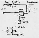
You can add a relay to short the output down to ground. (A small series resistor of 100 Ohms between LP output and RCA connector might be necessary if it's not already there). The relay should be controlled by the same signal that controlled the muting transistors before.
That way, you will have a functional muting circuit without additional relay contacts or semiconductors in the signal path.
Unlike adding those bleeder resistors, it will cure the turn-on/off pops.
That way, you will have a functional muting circuit without additional relay contacts or semiconductors in the signal path.
Unlike adding those bleeder resistors, it will cure the turn-on/off pops.
If your power switch is wired through the transformer secondary, then before too long a 'pop' on turn on or turn off will be the least of your problems.I have added 22,000 uf filter caps to my integrated amp and 15,000 uf filter caps to my cd player.
Increased power supply capacitance will mean a greater
current surge during the first few half-cycles at turnon. If
the power switch is wired to the secondary windings, the
current will be greater.
The risk here is that the switch contacts will burn out. There
may be a risk of blowing out the rectifiers, too. The latter
could be more damaging to circuit boards and components
if the fuse doesn't blow out very shortly thereafter.
I have a DIY amplifier based on the Leach design with a quarter
Farad of capacitance in the power supply; by using a double
throw center-off switch, I can start the amplifier through a
6 ohm surge limiting resistor. You might want to consider a
thermistor (high resistance cold, low resistance warm or hot)
in the switch circuit.
It >might< help to put a small capacitor, say .01 to .1, rated for
AC line use, across the switch contacts to reduce arcing. Possibly a RC snubber instead of the capacitor, but I'd have to experiment to guess at appropriate values.
I think your turn-on pops are more a 'feature' of the circuit design, which is why there is a muting circuit.
I've worked on a lot of amps with 'frozen' power switches, and these with 'stock' values of PS caps. The current surge is huge with the values of caps you are describing. Expect failure of the switch regardless of if you add a cap (mains rated!!) to the switch or not.
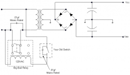
Since you are in there digging around anyway, perhaps consider using the power switch to operate a relay (nice, hefty one)...let the relay carry the current, not the switch. This is how it is done on a lot of high-end amps with tons of µf capacitence.
Since you are in there digging around anyway, perhaps consider using the power switch to operate a relay (nice, hefty one)...let the relay carry the current, not the switch. This is how it is done on a lot of high-end amps with tons of µf capacitence.
Echo Wars,
I will do some research on how to install a relay into my amplifier to 'carry the current' as you described.
A little bit more info:
When I turn the amplifier off, it still runs for about 30 seconds as the caps are discharging. The 'pop' that I hear through my speakers happens at the very end of this discharge process. (I can see the power on indicator LED slowly dimming and then go out as the 'pop happens)
This 'pop' noise has gotten worse the last few days. I do not know what to make of this.
I checked the schematic and the switch in the amplifier has a 'spark arrestor' installed across the switch. Is this the same as the cap you were talking about?
Would you be able to suggest what kind of relay to use and how to hook it up? Any help would be appreciated.
Thanks
KevinLee
This won't cure the pops.
While at it, why not bypass the relay contacts with a nice 20W resistor, put the power switch back in series with the relay contacts and use a secondary rail to power the relay. This will make a nice "soft start" circuit - your caps and rectifiers will live longer.
To cure the popping sounds during power up and shutting down, you can add a speaker protection circuit with a second relay.
Maybe you can show me where I said it would...AMT-freak said:This won't cure the pops.

You're talking about one problem, I'm talking about another.
However, soft turn-on would be a good addition. Draw something up there Freak..
My last post on this since KevinLee seems to have lost interest.
This circuit does as you described AMT, but adds a capacitor discharging resistor (the 150-ohm 10W at top) for when power is removed (as long as the power switch is at least a DPDT, this can be used).
All Elecronics has a 70-amp 24VDC relay here. It draws around 80mA, so I thought it wise to steal the voltage from both the pos and neg rails, as well as increasing the series resistor to 100 ohms since taking voltage from both rails means that the relay will turn on too fast with a 3-ohm resistor. The unknown resistor value of course will be determined by the rail voltages.
The 100-ohm 20W and 150-ohm 10W can both be had very cheaply from Parts Express. If I was going to do this, I might even try a 680-ohm 20W resistor and see what kind of delay it gives me. Probably too much, but PE selection of 20W resistors is kinda lean. Other values would have to be sourced elsewhere (Digikey).
Attachments
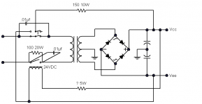
Sounds good, although a longer delay is not necessarily better - the series resistor might easily be overloaded, even if its rated for 20W. The circuit above or varations thereof is used in many commercial amps with toroids (Accuphase and others).
Btw, we both forgot about the flyback diode across the relay coil.
Btw, we both forgot about the flyback diode across the relay coil.
- Status
- This old topic is closed. If you want to reopen this topic, contact a moderator using the "Report Post" button.
- Home
- Amplifiers
- Solid State
- Bleeder Resistor Advice