I can't seem to find any info on this so will start a new thread. I am building another Symasym amp to power planar tweeters in a 3 way active setup. My plan is to use regulated +/-30V supplies and also to increase the circuit bias to give mabye 4W of class A power. Load is 8 ohms, very much flat with the planars and active setup.
I will be using the 1943 and 5200 type output devices mounted on a 0.4c/w heatsink per amp. I am hoping to build today (am matching signal transistors right now!) but need to make it so that I can set the bias suitably high (since it is not designed for such high bias?). What will need to be changed to allow a suitable bias for 3-4W class A? Or mabye it will already do this (my other one didn't look like it though with the pot nearly all the way round for the typical 55ma bias).
Any help appreciated!
I'm running my Symasym monoblocks with 350mA bias (+/-32V rails). Output devices are MJL21193/4 on fairly big heatsinks. They do turn pretty hot.
My initial target was on the 700mA side, but I think I need to add more output devices (I was thinking 3 per side) to reach it. As I don't have an appropiate way of measuring the heatsink's temperature (other than my multimeter's termocuple, and I kinnda' don't trust it) I just don't want to push it any harder given the summer temperatures these days.
I am running the monoblocks full range but as I increased (in little steps follwed by several hours/days of listening after each step) the bias current I noticed the sound getting sweeter and more detailed specially in the upper treble range.
Anyway, I am very curious about your findings. Good luck with your build!
Your results are very promising! 350ma bias gives about 2W into 8ohm of class A? Not sure how to calculate it. Also what voltage should I look for accross the 0.22r output resistors to set this 300-350ma bias current? Can it be set this high without changes to the design or must changes be made to allow setting of this higher bias? Let me know what changes must be made if there are any! Many thanks ")
For 350mA bias current you should measure aprox. 150mV across both 0.22R. But be carefull, my output tranzistors are rated at 200W dissipation if I remember corectly.
There are no changes for you to make to the original Symasym 5.3 by Mike Bittner.
I suggest you do the bias increasing in steps and watch over the heatsink's temperature. They will get hot, although your heatsinks seem quite big at 0.4 C/W.
One mod I made to the original design was changing the input long tailed pair tranzistors to 2sk170B. It's really a worthwhile change. (Does nothing to do with the bias current increase)
Keep up the good work and keep us posted!
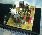
Thanks very much for your help! I shall carry on building as per the original design and will certainly keep you posted . The heatsinks are 30cm by 10cm with 3cm fins on a 1cm base, all anodised black aluminium. They form the sides of the case too so are in direct contact with the air for good convection. The transfer from transistor to heatsink will be most critical, I plan a mount with allen bolts and quality Sil pads, should do the trick
. The heatsinks are 30cm by 10cm with 3cm fins on a 1cm base, all anodised black aluminium. They form the sides of the case too so are in direct contact with the air for good convection. The transfer from transistor to heatsink will be most critical, I plan a mount with allen bolts and quality Sil pads, should do the trick One amp is just about ready for testing. I ideally need to get the allen type mounting bolts and change those 1.2ohm resistors for correctly rated ones (they are 1W but should be 2W, will do for testing). I'm off out soon so will get back to you tomorrow, hopefully it works! The overall mounting scheme is much tidier and simpler than my previous build
Attachments
Looks like a nice clean build! I noticed you didn't use the recommended wimas for by-passing.
One more advice, use extra capacity for the power supply capacitors as the increased power in class A will drain them much faster.
For example, my 2x33.000uF per monoblock only last for 3-4 seconds after I switch of supply power, vs. 10-15 seconds with the recommended bias setting (55mA).
One more advice, use extra capacity for the power supply capacitors as the increased power in class A will drain them much faster.
For example, my 2x33.000uF per monoblock only last for 3-4 seconds after I switch of supply power, vs. 10-15 seconds with the recommended bias setting (55mA).
go back to basics.
required maximum ClassA output power = 4watts.
Lets assume the driver is 8ohm impedance.
Required output voltage for 4W into 8r0 = sqrt[2*P*Rload]=8Vpk.
check:-
8Vpk across 8ohms results in 1Apk
P=Ipk*Ipk*Rload/2= 1*1*8/2=4W.
Your load only needs 8Vpk and 1Apk to meet your 4W max power requirement.
Assume that the voltage losses through the amp are 5Vpk when delivering max current.
The PSU supply rails need ~ 8Vpk+5Vpk ~+-13V. Not +-30V
For a push pull amplifier the quiescent current in the output stage ~Ipk/2 ~ 500mA. Add 50mA to avoid non linearities as ClassA limit is approached.
Heatsink dissipation ~=0.55*[13+13]~=15W shared between two transistors.
Will the symasym work on +-13Vdc, probably not, it requires a redesign. Or choose another source circuit.
I got 100 of those little yellow box capacitors, they seemed to work in my other symasym, still polyester, 63v.
I plan a regulated supply, the design is here:
http://www.diyaudio.com/forums/showthread.php?s=&threadid=56106&highlight=
This should eliminate noise problems you can get with class A. Will I still need extra capacitance before the regulators though say? Bear in mind there are no big bass peaks to handle!
I probably wasn't clear enough in my first post. I proposed 4W class A power (roughly) but by using the supply of +/-30V I would still have mabye 40-50W power on tap, albeit in class AB. It is for tweeters so the 4 watts will probably cover most circumstances but as you have often said it is still wise to have headroom with tweeters to cover possible peaks. I figure I can live with these being handled in class AB and 3-4W of class A strikes a reasonable balance.
The maths is good to see, might be able to manage the 550ma quiescent if it is only 7.5W per package. The total 15W gives only a 6c temp rise with my heatsinks (ignoring insulators etc). There will also be regulator chips on the same sinks though adding about 3W quiescent dissipation.
I don't think you should worry about class A noise problems since this is not a "real" class A amplifier.
I really don't know if it will benefit much from the regulated supply proposed. I guess it wouldn't harm to try both ways and see the differences. But since I'm not much of an expert better wait for a second opinion on that, especially given the fact that the psu was designed for chipamps.
I really don't know if it will benefit much from the regulated supply proposed. I guess it wouldn't harm to try both ways and see the differences. But since I'm not much of an expert better wait for a second opinion on that, especially given the fact that the psu was designed for chipamps.
I expect it will make little if any difference over a well smoothed standard DC supply. Either way I have the parts so will probably do it regardless, don't think it can do any harm, not with treble anyhow; with bass it might not be solid enough for the high current demands. The snubber section might be unrequired since I believe it only works properly with the chipamps.
Dr.EM said:One amp is just about ready for testing.
I believe you will get better efficiency from the heatsink if you mount it with the fins running vertical and the transistors mounted at the bottom of the heatsink. (turn the board 90deg)
André
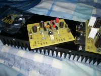
The heatsink will be mounted so that its fins are vertical when finished, this was just easy to photograph. The heatsink forms the sides of the case and the fins are all on the outside.
If you mean rotate the board on the sink then it wouldn't fit. It literally just fits the way it is (100mm sink, 100mm board, needed some sanding of the board to allow the case top and bottom to be fastened).
Hopefully it will be enough this way anyhow, the traditionally biased Symasym makes a barely noticeable change to heatsink temperature even after hours are normal volume.
I have nearly finished the second board incidently. The first seems to work but I haven't set up a proper test yet. Got to build these regulators but need some plain clad board to do it.
I found my allen bolts so put them in. Much firmer than crosshead etc. Yes, I will be applying thermal compound to the micas but I know I will have to take that board off (to change resistors and solder leadouts) so will do it in the final assembly only.
Attachments
Oops, I didn't realise that . Should have read those sums more carefully. Ok, mabye around 360ma to give about 1.6W class A power will be more reasonable, 21.6W dissipation between the 2 transistors. Surely they can cope with this on a 0.4c/w heatsink with no problems? They are 150W devices, so less than al3xu's 200W ones but surely they won't be derated to 10W or so used this way?
Tweeters are 93db sensitivity each (closer to 95 accross much of the band) so the 1.6W will still give about 100db at 1m which should be a lot above 4khz. Having the 40W per channel AB headroom is still nice though.
. Should have read those sums more carefully. Ok, mabye around 360ma to give about 1.6W class A power will be more reasonable, 21.6W dissipation between the 2 transistors. Surely they can cope with this on a 0.4c/w heatsink with no problems? They are 150W devices, so less than al3xu's 200W ones but surely they won't be derated to 10W or so used this way?Tweeters are 93db sensitivity each (closer to 95 accross much of the band) so the 1.6W will still give about 100db at 1m which should be a lot above 4khz. Having the 40W per channel AB headroom is still nice though.
Ok, figured it would be best to try this out to judge for myself. Connected the amp to the power supply in my existing symasym which gives +/-36.5V measured. I went through the maths to set the amp so it was dissapating 21.6W. Been on for mabye an hour now, gets pretty toasty. It all feels pretty manageable though, the heatsink is nicely warm, could keep your fingers on it indefinately but it is uncomfortable. The plastic part of the output transistors are similar. Its cooler than a 3W resistor running at 0.6W anyhow which I really can't keep my finger on (its just inside the amp so is convenient!).
Issue might be more the effect on the room, its getting really stuffy in here now! I am sat right near it but it seems to be having a suprising effect on ambient temperature. I think 1W class A each channel might have to do it (about 16W dissapation each channel).
There is some buzzing/humming from the speaker too. I am assuming this is because he power supply can't cope, its 15,000uF per rail, so not huge (still running 1 normally biased Symasym too).
Tell me about room temperature! This evening I tried to listen to some music but after about half an hour I concluded that it really is to hot for this sort of thing.
In my small room, with the computer, a CRT monitor, the monoblocks and the tube preamp it's just to much. Lucky me I get the livingroom for a month or so pretty soon (has air conditioning and it's a whole lotta larger so I think the sound will benefit from this change).
Strange thing with the buzzing/humming. 15000µF per rail really isn't a modest value (for a single channel?).
Did you noticed any improvements over the normally biased Symasym?
Its cooled off now, switched everything off and threw the window open for a bit
The grounding may not have been optimal in this test setup, so that may also be to blame for the buzzing; it was only 1 channel. I suspect i'll need more than the suggested 4700uF on the regulated supply. I have some more 4700uF caps around so will likely put a pair on each rail to give about 15000uF before each regulator. The ripple must be quite large to cause audible noise with an AB design? Could check it out with the scope I guess.
Haven't got as far as really analysing the sound since it was mono and only a quick test with the MD portable but once complete I'll be in a good position to do so (having both normal and overbiased amps).
Ok, so I guess I'll keep my fingers crossed and wait for the result. I really want a second opinion on what I've heard.
I have a forum friend here in Romania who biased in class A a DX-amp with very good results. He reached a promising 750mA but I have no ideea if he kept only one pair of tranzistors. The point is that he said after 300mA the sound was getting a whole new dimension on the hights. I felt that with Symasym to a point to, but it's a pitty I could not go further with the investigation. I'm thinking adding forced cooling for further tests.
I have a forum friend here in Romania who biased in class A a DX-amp with very good results. He reached a promising 750mA but I have no ideea if he kept only one pair of tranzistors. The point is that he said after 300mA the sound was getting a whole new dimension on the hights. I felt that with Symasym to a point to, but it's a pitty I could not go further with the investigation. I'm thinking adding forced cooling for further tests.
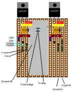
I will likely be doing this regulator on striboard, due to lack of other resources. It shouldn't be an issue, I will have a ground fill (ie, large low resistance area), and the input and outputs should be handled by stripboard tracks. I checked stability with a breadboard model and its fine; though interestingly 100nf ceramic discs didn't seem to work in place of 47nf polys? It oscillated with them, I thought they were better for decoupling, they have seen better days though
Attachments
- Status
- This old topic is closed. If you want to reopen this topic, contact a moderator using the "Report Post" button.
- Home
- Amplifiers
- Solid State
- Symasym biased for class A