Hello everyone,
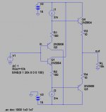
Recently (since this morning actually) I got very interested in diamond buffers and found several schematics. I understand the principle for the Walt Jung version and some derived ones but not this one for which I post the schematic. I may be a dumb question but how is the second stage correctly polarised? To me it looks like a class B or even C stage... Probably I'm missing something in the design...
Recently (since this morning actually) I got very interested in diamond buffers and found several schematics. I understand the principle for the Walt Jung version and some derived ones but not this one for which I post the schematic. I may be a dumb question but how is the second stage correctly polarised? To me it looks like a class B or even C stage... Probably I'm missing something in the design...
Attachments
Thank you for your answer,
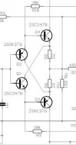
These ones have the emitter resistor for bias as it should. I just wondered about the scheme without them. I found it on a forum about headphones. They could be Sijosae design or something. I just wondered about the crossover distortion in a strict class B like that. It is better in class A.
And if the Vbe of the first stage is lower than the second, you get a nice class C one.
I may be wrong but I wanted a confirmation.
Anyone?
Darian
I read the circuit (1) like this: -
The circuit is symmetrical and collector voltages in the first stage will be equally offset from the supply rails when the Hfe of the transistors is equal.
Since the bases of the input transistors are at the same voltage (connected), the differential voltage between the collectors is Vbe(337) + Vbe(327). This is insufficient to bias the second stage into conduction, because of the voltage drop across the 2*4R7 emitter resistors and because the transistors used are identical to the ones in the first stage.
So this is a class B push-pull amplifier and will have pronounced crossover distortion.
w
Thanks for your answer,
So I was right about it. I guess no one complained about it in the headphone forum (Headwize I think). There may be some people listening to that badly designed circuit and thinking it's a good one. Too bad for them...
Anyway, I have my answer. If someone wants to try the Accuphase circuit, I'd be pleased to hear some feedback. It's so smart and so simple at the same time.
Thanx
wakibaki said:
The circuit is symmetrical and collector voltages in the first stage will be equally offset from the supply rails when the Hfe of the transistors is equal.
Since the bases of the input transistors are at the same voltage (connected), the differential voltage between the collectors is Vbe(337) + Vbe(327)
Sorry
I was about to go to bed when I wrote that. I went to sleep and woke up thinking about it.
In both instances this should read emitter, not collector.
This is 2 cross-coupled emitter followers, so voltage gain < 1. It's purely a current buffer.
Since the Vbe's of the stages are likely to be close, the xover is probably fairly smooth.
If you wanted to run it AB, you could do this:-
An externally hosted image should be here but it was not working when we last tested it.
w
The accuphase circuit is interesting indeed, harmon kardom uses it as well. I think this type of circuit is mentioned in hawksford paper | Reduction of transistor slope impedance dependence distortion |, but i cant remember if it was that exact circuit. Maybe someone here has already compared it to the jung circuit in some thread. Ive only seen one diy guy here use it, maybe it has issues like stabilty. Hawksfords circuits perform well but suffer from oscilations.
The 1st buffer mentioned is biased in class A .. the output pair is biased at only little less current than the input pair..
3mA from + -15Volts, and 1.17mA for + -5 Volts..
The finite transductance of the input pair, will cause enough BEvoltage drop for the output pair to draw significant current.
grt, T
3mA from + -15Volts, and 1.17mA for + -5 Volts..
The finite transductance of the input pair, will cause enough BEvoltage drop for the output pair to draw significant current.
grt, T
Hi,
PMA's buffer on the output of his new dis pre is virtually identical to headwise buffer.
http://www.diyaudio.com/forums/showthread.php?postid=1509817#post1509817
It appears that if the Vbe values are chosen appropriately that the two stages in the buffer remain in ClassA.
There is an updated version later in the dis pre thread.
tschrama said:The 1st buffer mentioned is biased in class A .. the output pair is biased at only little less current than the input pair..
3mA from + -15Volts, and 1.17mA for + -5 Volts..
The finite transductance of the input pair, will cause enough BEvoltage drop for the output pair to draw significant current.
grt, T
OK, a fuller description of the mechanism would be appreciated, thanks.
w
Hi Peranders,
Thanks for the lme49600.
Only problem i find with chip based circuits is subjective. A well implemented diamond buffer using good transistors always sounds better to me. I find it strange as the two chips are well designed and have excellent performance data. Dont get me wrong a chip like buf634 is by no means bad at all but ......... Maybe its something to do with the auxilary circuits within these chips..... Impresions on the lme49600???
What do think of the accuphase circuit???
By the way congrats, you have some interesting designs on your website.
Alex
OK, I had another look at this. I guess in matched transistors at the same temperature the Vbe's in the first stage at about 4.8mA have sufficient drop across them to cause a mirrored current in the output stage of 4.8mA except this is reduced because of the emitter resistors.
Only took about 12 hours for the penny to drop.
Thanks for chipping in.
w
Only took about 12 hours for the penny to drop.
Thanks for chipping in.
w

Sorry but I don't totally get it even now. As I understand it, the bias is extremely low at the best in the second stage. Even if we consider "the finite transconductance" of the first transistor, we get a collector voltage of 0,6 plus a very small fraction of percent of it right? This very small fraction divided by the value of the emitter resistor of the second transistor will be the idle current at the output, let's say it's very very tiny. And that's if we tightly match the Vbe so the first transistor has one equal or superior to the one of the second transistor or it will end in class C right? So much trouble for that! Better go class A no?
I think almost all Head-Fi:ers use emitter resistors on the input stage in their diamond buffers, inspired by designers like Amb, PPL and Tangent. Even Sijosae used emitter resistors in his first version. There are many versions out there. Maybe the one above was intended for long battery life since it was designed several years ago when rechargeable batteries were expensive and with a lot lower energy storage than the ones we use nowadays.darian said:Thanks for your answer,
So I was right about it. I guess no one complained about it in the headphone forum (Headwize I think). There may be some people listening to that badly designed circuit and thinking it's a good one. Too bad for them...
- Status
- This old topic is closed. If you want to reopen this topic, contact a moderator using the "Report Post" button.
- Home
- Amplifiers
- Solid State
- A question about diamond buffers