Hello, all.
I was recently looking at Doug Self's site and just got through reading every single page relating to OPamp, discrete, and power amplifier design.
Much to my surprise, It all made sense to me, and fell comfortably in place with all that I have learned through messing around on the simulator and playing with my oscilloscope.
For instance, I now understand how emitter resistors cut down on switch noise in class B/AB amps, and also serve to help linearity. I understood all of his article on the CFP or Sziklai pair and also his page debunking what he said to be 98% of all commercial amplifier designs nowadays.
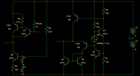
So when I got done reading and went back to the simulator, I also realized how similar a circuit I had currently been mutating was to the CFP emitter-follower.
Can you tell how they are fundamentally the same?
The second circuit is mine, and was intended to be an ultra-high impedance dynamic mic preamp.
This really amazed me when I realized what I had done. I now fully understand why my own circuit gives such great performance, thanks of course to D. Self and his Amplifier Institute.
Cheers to cyber-electrical engineers, I am truly glad I've been able to get this far without paying too much $$. 0_0
- keantoken
I was recently looking at Doug Self's site and just got through reading every single page relating to OPamp, discrete, and power amplifier design.
Much to my surprise, It all made sense to me, and fell comfortably in place with all that I have learned through messing around on the simulator and playing with my oscilloscope.
For instance, I now understand how emitter resistors cut down on switch noise in class B/AB amps, and also serve to help linearity. I understood all of his article on the CFP or Sziklai pair and also his page debunking what he said to be 98% of all commercial amplifier designs nowadays.
So when I got done reading and went back to the simulator, I also realized how similar a circuit I had currently been mutating was to the CFP emitter-follower.
Can you tell how they are fundamentally the same?
The second circuit is mine, and was intended to be an ultra-high impedance dynamic mic preamp.
This really amazed me when I realized what I had done. I now fully understand why my own circuit gives such great performance, thanks of course to D. Self and his Amplifier Institute.
Cheers to cyber-electrical engineers, I am truly glad I've been able to get this far without paying too much $$. 0_0
- keantoken
Attachments
Nice to see you designing interesting circuits 
At last!!
Yes, this works basically on the same principle that CFP.
I guess you know that you are forcing some DC current flow through input source. This shouldn't do any harm to a microphone, but when the microphone is disconnected, the output will stick to negative rail.
Regards
Adam
At last!!
Yes, this works basically on the same principle that CFP.
I guess you know that you are forcing some DC current flow through input source. This shouldn't do any harm to a microphone, but when the microphone is disconnected, the output will stick to negative rail.
Regards
Adam
Thank you, exactly what I thought!
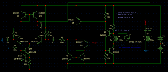
Yes, I know. The downfall is that condenser mics won't work because there must be DC running through. So the circuit is basically limited to some kind of coil, e. g. that of a dynamic microphone. I've also been toying with the thought of the input coming from a transformer, with feedback and such as in the circuit below.
So if using a microphone, unplugging will cause all of R2's current to go through Q1's base - starting off the chain reaction of doom. I haven't thought of a solution to this problem yet. So the circuit would best be used for now in a built-in preamp to a dynamic mic so it can't get disconnected.
In all, I think this would make a superb coil-pickup device for getting phone conversations or looking for magnetic interference. Listening to your hard drive do it's thing.")
- keantoken
Yes, I know. The downfall is that condenser mics won't work because there must be DC running through. So the circuit is basically limited to some kind of coil, e. g. that of a dynamic microphone. I've also been toying with the thought of the input coming from a transformer, with feedback and such as in the circuit below.
So if using a microphone, unplugging will cause all of R2's current to go through Q1's base - starting off the chain reaction of doom. I haven't thought of a solution to this problem yet. So the circuit would best be used for now in a built-in preamp to a dynamic mic so it can't get disconnected.
In all, I think this would make a superb coil-pickup device for getting phone conversations or looking for magnetic interference. Listening to your hard drive do it's thing.
- keantoken
Attachments
keantoken,
I have read some of the stuff you posted lately and it shows that you have a better understanding of electronics than you did 18 month ago. However, I would like to give you a little constructive feedback on the right hand circuit of post #1. You may actually learn something from this. It took me a while to figure out what the circuit did, but it is essentially a very complex emitter follower formed by Q6. Here are the comments.
1. The impedance at the base of Q1 is relatively low. Therefore, the voltage there will not change much when an AC signal is applied. The upper terminal of Vin might as well be connected to ground. Thus Q1 and Q2 could be eliminated.
2. The impedance looking out of the lower terminal of Vin is very large. Thus most of the input voltage will appear at the base of Q6.
3. Q3 and Q4 perform no useful function. Delete them. Connect the collector of Q6 to -6.
4, Q5 is essentially a constant current source - but not a very good one. It could be replaced by a resistor of 5K to 10K. Actually, a good constant current source could reduce distortion, but it is probably not worth it.
So all that is left is the voltage source connected to ground and the base of Q6, Q6 with an emitter load of 10K connected to +6 and it's collector connected to -6.
keantoken, it turns out that almost all of the brilliant circuit have already been discovered. Almost all new designs are based on previous work. We may use newer and better devices, but there are only so many ways to make a voltage follower, or an op amp, or a sinusoidal oscillator, or a comparator, or a square wave oscillator, etc.
Please let me know, if I misunderstood your circuit.
Rick
- Status
- This old topic is closed. If you want to reopen this topic, contact a moderator using the "Report Post" button.