Hello, all.
I've been messing with this design in the simulator for quite a while as a Dynamic mic preamp, among other things. It's interesting, definitely not mainstream as far as I know.
I was able to get decently low distortion, at least from what the sim says. I haven't got around to building it because frankly I have no idea which of my transistors are blown and which are not!
At any rate, the only thing I can see which might be a problem is the offset current passing through the mic. I don't know much about mics but I don't think this is enough to cause it to distort.
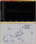
The input isn't the normal type. It actually uses the two-transistor CCS arrangement. In effect, this is a very high-impedance input because any voltage across the mic causes a shift in Q2's bias, which is quickly nulled by Q1 regulating the current through the mic.
The output is taken from Q1's collector, and this is the main output signal.
To power Q3, we attach a transistor to R3. This is the feedback.
If the input circuitry is inadequate to cancel out current through the mic, then this will show up as fluctuations in the output of the "CCS" input pair. Thus, these fluctuations nullify distortion in the main output path.
The output of the circuit as a whole is R4.
It doesn't really amplify voltage, it simply multiplies the amount of current available so technically it's an impedance matching circuit.
At any rate, I would like feedback on this design as well as concerns that I may have missed. I've been tweaking this circuit for quite a while, so now I'll listen to what the more experienced guys have to say.
Concerns? Advice?
- keantoken
I've been messing with this design in the simulator for quite a while as a Dynamic mic preamp, among other things. It's interesting, definitely not mainstream as far as I know.
I was able to get decently low distortion, at least from what the sim says. I haven't got around to building it because frankly I have no idea which of my transistors are blown and which are not!
At any rate, the only thing I can see which might be a problem is the offset current passing through the mic. I don't know much about mics but I don't think this is enough to cause it to distort.
The input isn't the normal type. It actually uses the two-transistor CCS arrangement. In effect, this is a very high-impedance input because any voltage across the mic causes a shift in Q2's bias, which is quickly nulled by Q1 regulating the current through the mic.
The output is taken from Q1's collector, and this is the main output signal.
To power Q3, we attach a transistor to R3. This is the feedback.
If the input circuitry is inadequate to cancel out current through the mic, then this will show up as fluctuations in the output of the "CCS" input pair. Thus, these fluctuations nullify distortion in the main output path.
The output of the circuit as a whole is R4.
It doesn't really amplify voltage, it simply multiplies the amount of current available so technically it's an impedance matching circuit.
At any rate, I would like feedback on this design as well as concerns that I may have missed. I've been tweaking this circuit for quite a while, so now I'll listen to what the more experienced guys have to say.
Concerns? Advice?
- keantoken
Attachments
Here is the result of a .four analysis:
-----------------------------------------------
Harmonic Frequency Fourier Normalized Phase Normalized
Number [Hz] Component Component [degree] Phase [deg]
1 5.000e+03 9.941e-03 1.000e+00 -180.00° 0.00°
2 1.000e+04 1.447e-08 1.455e-06 84.52° 264.51°
3 1.500e+04 8.261e-11 8.310e-09 23.05° 203.05°
4 2.000e+04 1.214e-10 1.221e-08 103.68° 283.68°
5 2.500e+04 1.673e-10 1.682e-08 132.73° 312.73°
6 3.000e+04 2.133e-10 2.145e-08 147.30° 327.30°
7 3.500e+04 3.090e-10 3.108e-08 160.75° 340.75°
8 4.000e+04 3.418e-10 3.438e-08 160.03° 340.03°
9 4.500e+04 3.876e-10 3.899e-08 161.21° 341.20°
Total Harmonic Distortion: 0.000146%
------------------------------------------------------------------------------
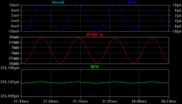
This is at an input level of 10mV. I estimate that the input pk-pk value is about .6pA (the sim doesn't give smaller values). Output into 1k gives 10uA pk-pk, with slightly larger distortion than with 1mV input. I'll assume this is as close to the limit as we want it.
So 5uA/.3pA= ~33,000,000 in current gain.
So for this to be an 'official' preamp, I would have to add a VAS to give about 2V pk-pk output, right?
I've been messing around with other variations of this circuit. Apparently it's not only useful as a mic preamp.
- keantoken
-----------------------------------------------
Harmonic Frequency Fourier Normalized Phase Normalized
Number [Hz] Component Component [degree] Phase [deg]
1 5.000e+03 9.941e-03 1.000e+00 -180.00° 0.00°
2 1.000e+04 1.447e-08 1.455e-06 84.52° 264.51°
3 1.500e+04 8.261e-11 8.310e-09 23.05° 203.05°
4 2.000e+04 1.214e-10 1.221e-08 103.68° 283.68°
5 2.500e+04 1.673e-10 1.682e-08 132.73° 312.73°
6 3.000e+04 2.133e-10 2.145e-08 147.30° 327.30°
7 3.500e+04 3.090e-10 3.108e-08 160.75° 340.75°
8 4.000e+04 3.418e-10 3.438e-08 160.03° 340.03°
9 4.500e+04 3.876e-10 3.899e-08 161.21° 341.20°
Total Harmonic Distortion: 0.000146%
------------------------------------------------------------------------------
This is at an input level of 10mV. I estimate that the input pk-pk value is about .6pA (the sim doesn't give smaller values). Output into 1k gives 10uA pk-pk, with slightly larger distortion than with 1mV input. I'll assume this is as close to the limit as we want it.
So 5uA/.3pA= ~33,000,000 in current gain.
So for this to be an 'official' preamp, I would have to add a VAS to give about 2V pk-pk output, right?
I've been messing around with other variations of this circuit. Apparently it's not only useful as a mic preamp.
- keantoken
Attachments
I guess you will find some good use for this topology.
The current gain is impressive, from such relative few transistors circuit.
And at the level you did your test, harm. dist. is very low.
For mic preamps / RIAA, it is many time a good idea to use battery supply.
One or two 9 V (for +-9 supply).
This is the easy way, to solve the mains ripple, from being amplified.
Batteries are good for some special applications.
But then there is problem to keep down consumption .. so they will last for some months of work.
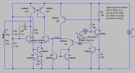
Alright. The first thing to do off my mind would be to add an LTP, so here it is.
Distortion:
--------------------------------------------------------
Fourier components of V(vout)
DC component:1.54604e-006
Harmonic Frequency Fourier Normalized Phase Normalized
Number [Hz] Component Component [degree] Phase [deg]
1 5.000e+03 7.589e-02 1.000e+00 179.95° 0.00°
2 1.000e+04 7.054e-07 9.295e-06 85.51° -94.44°
3 1.500e+04 7.085e-09 9.336e-08 176.57° -3.38°
4 2.000e+04 1.511e-09 1.991e-08 141.93° -38.02°
5 2.500e+04 2.358e-09 3.107e-08 144.81° -35.14°
6 3.000e+04 2.631e-09 3.467e-08 160.43° -19.52°
7 3.500e+04 2.640e-09 3.478e-08 166.68° -13.28°
8 4.000e+04 3.656e-09 4.818e-08 158.15° -21.80°
9 4.500e+04 3.561e-09 4.693e-08 162.31° -17.64°
Total Harmonic Distortion: 0.000930%
-------------------------------------------------------------------------------
Feedback is via R8. Output is just below 80mV pk-pk.
So this is about 8 voltage gain. Pitiful. I would need about 25 of these before I would have what I wanted. Then again I don't know what's expected of a preamp.
I'm not sure how to go about biasing the LTP, other than doing it the good 'ol babylonian way. I know that in Symasym Mike did it by putting the bias directly on ground. That doesn't work here though, because my output is directly from the LTP and that will always be some mV above bias.
At any rate, distortion was multiplied by the same amount as the voltage, which means I am only amplifying distortion that was present in the input circuitry. I take it that's good, because (as it seems) no extra distortion is being injected by the LTP.
Note: changing R8 to 1k improves distortion considerably, but at 33mV pk-pk. This is only a gain of about 3, however. Does make me think, though. A POT could be inserted here for volume control.
- keantoken
Attachments
- Status
- This old topic is closed. If you want to reopen this topic, contact a moderator using the "Report Post" button.