I have an Adcom GFA-555 MKII. I've had it repaired before, because it popped, and went on fire while it was on and sitting idle. An authorized adcom service center fixed it, for $350 or so, and made sure to replace parts that had to be matched with matching parts.
Half a year later, and it is broken again. I don't remember if it broke as I turned it on, or if it broke while it was already on.. I think I was playing music, the right speaker made some odd noise and went off, and when I checked the fuse for the right channel was blown. I got a new fuse of the same rating, and the same thing happened.. I turn it on, the speakers do the little dance they do for the first second it is on, and the fuse blows as the right speaker makes a funny noise.
This time around I'd rather try to fix it myself. I have done work on line level and mic level preamps before as a "tech" but I make no claim to know what I am doing with direct coupled power amps... or hell, power amps in general. most of what I get to fix, I learn how to fix as I am fixing it! Since the cost of having this repaired will probably be as much as getting another used gfa-555 MKII, I've decided this would be a great time to jump into the world of power amps, and learn as much as I can through trial and error as I attempt to repair this.
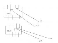
I was told by a very helpful, patient person at adcom that it is probably shorting output devices, and that I should check the reference output of IC101(Adcom 3A, which seems to be the DC servo thing on the left channel) and IC151(Adcom 3A, DC servo thing on the right channel), and see if there is a difference. I was also told that the transistors are probably fine as it is the fuse blowing that keeps the transistor from becoming FUBAR.
From searching this board it appears that the AD820 is a good choice for replacement, if this is indeed the faulty part.
I was looking for some advice and direction on what else to look for. I apologize as this probably is a retarded question for any of you who actually know what you are doing, but I would highly appreciate any assistance one with more experience and knowledge could throw my way. Thanks in advance for any help you can provide, before I go tinkering inside this beast.")
Half a year later, and it is broken again. I don't remember if it broke as I turned it on, or if it broke while it was already on.. I think I was playing music, the right speaker made some odd noise and went off, and when I checked the fuse for the right channel was blown. I got a new fuse of the same rating, and the same thing happened.. I turn it on, the speakers do the little dance they do for the first second it is on, and the fuse blows as the right speaker makes a funny noise.
This time around I'd rather try to fix it myself. I have done work on line level and mic level preamps before as a "tech" but I make no claim to know what I am doing with direct coupled power amps... or hell, power amps in general. most of what I get to fix, I learn how to fix as I am fixing it! Since the cost of having this repaired will probably be as much as getting another used gfa-555 MKII, I've decided this would be a great time to jump into the world of power amps, and learn as much as I can through trial and error as I attempt to repair this.
I was told by a very helpful, patient person at adcom that it is probably shorting output devices, and that I should check the reference output of IC101(Adcom 3A, which seems to be the DC servo thing on the left channel) and IC151(Adcom 3A, DC servo thing on the right channel), and see if there is a difference. I was also told that the transistors are probably fine as it is the fuse blowing that keeps the transistor from becoming FUBAR.
From searching this board it appears that the AD820 is a good choice for replacement, if this is indeed the faulty part.
I was looking for some advice and direction on what else to look for. I apologize as this probably is a retarded question for any of you who actually know what you are doing, but I would highly appreciate any assistance one with more experience and knowledge could throw my way. Thanks in advance for any help you can provide, before I go tinkering inside this beast.
Since it's the 805 fuse that blew, would it make sense to swap the A035B card between channels, before I swap IC101 and IC151 between channels? If the problem follows, then look on the card.
I'm waiting on some of my tools to arrive before I start swapping things out.
Also in removing the cards, I'm guessing desolder the transistors from the card so I can pull them off the heatsink, and remove the card.. is there an easier or more logical way to do this? With computer stuff I always find out the sensible way after I've went the long way, and this has carried over into electronics.
thanks a lot.
Swapping A035B with A035D stops the fuse blowing on the left channel. I haven't put the transistors back into the right channel, because I had to catch a bus home before I was stuck with this thing for another seven hours....
interesting. Now to swap parts back and forth between A035B and A035D and see what's ****** up.
interesting. Now to swap parts back and forth between A035B and A035D and see what's ****** up.
ok, I switched the cards.
the right channel, which now has the left channel's negative transistor card.. worked for 30 seconds. It played music for half a minute, no blown fuse. Then there was a visible spark, no smoke but a mark on the board near that transistor, and it's dead.
I observe that point, and don't see anything.. I, like a dumbass, put a new fuse in to try again! and this time the capacitor going from the positive board's power rail to ground blows, and smoke explodes into the air, and the positive fuse blows.
I try the left channel, which has the right channel's negative transistor card(used to work), and it's bunk. It measures 70-80v AC on the multimeter, clicks the speakers, but no music, and no blown fuses.
Now, on the right channel(which has the left channel's negative card), I swap out the transistor that I figure blew(from the mark on the PCB), and switch it with another negative transistor from the other side, and notice as I am doing this that +v and -v are shorted to the bar attaching the positive and negative cards, for the left channel. WTF! I'm guessing this happened after the smoking event.
I am confused beyond belief now. Any insiht would be much appreciated!
Alright, this is probably my last plea for assistance before I give up on this project for good.
I took out both cards for the right side, cleaned them down with alcohol and a brush, put fresh transistors that weren't shorting into both cards. I checked for shorts wherever I imagined they could be.
I turn the thing on, and the negative card's fuse doesn't just blow.. it melts to an oblivion, and the four output transistors are totally shorted afterwards.
D:
I check the left side, which has two, not shorting output transistors on each side(instead of 4.. I stole some from this side to replace the blown ones on the right side). I turn it on and check this side. No blown fuses, but it puts out a steady 71.2v AC, that bears no relation to the audio input.
I tried switching IC151 with IC101(Adcom 3A), with no change.
I have no clue what is going on at this point. I am not sure why, every output transistor on the negative card for the right speaker blows immediately after turning it on, as well as blowing a fuse, after it played music for 40 seconds. I'm not sure why the capacitor blocking DC on the output, on the positive card, exploded before, but does not now.
Any insight highly appreciated.
Hi ����,
A more sensible user name might be in order.
I can see you have not read any threads on servicing these amplifiers. Anything you learned by repairing computers does not carry into amplifier servicing. For instance, you never, ever swap parts between channels. Myself and others have posted extensively on these amplifiers.
Just because one shop may not have serviced this amp properly (maybe they did and something else happened?) does not mean you should attempt this yourself. Now you have increased the amount of damage - and the cost of servicing. It's not the amplifier's fault that the damage occurred either.
At this point, I personally don't feel that you have the experience or mindset to successfully repair your amplifier. I'm not trying to be mean, just realistic about your situation. I imagine that you do have the service manual. What you have mentioned about getting tools frightens me a little too. You should have a decent DVM and an oscilloscope, or at least access to these items. A proper soldering station will be required, as will a solder sucker and wick. You need to replace the electrolytic caps to start (alcohol seeps in over time). The output transistors need to be matched before installation (that means you need to buy 10 ~ 15 pcs to match 5). You will need a good transistor tester that does measure leakage in two modes - or just replace the lot. Once again there are some that require matching.
Advice? Read those threads and be honest with yourself. Your amp probably should be in the hands of a good technician.
-Chris
Hey,
Thanks for the response!
I am quite certain I do not have the experience to repair this properly! I knew as much starting the project.
I'd like to make it clear that this is not about being faster, cheaper, better, or more efficient than hiring a good tech. Ironically, I fully support bringing stuff to people who know what they are doing already opposed to taking a DIY approach in my "regular" job field! Rather, I saw this as an opportunity to learn something and broaden my meager knowledge of electronics, from small line level amp circuits and whatnot to something else(power amps). I've enough receivers and amps around here collecting dust to keep my stereo playing for a long time, so it's not much of a deal if this doesn't work immediately.
The only threads I've read were the ones I could find at the time through googling with the site: appenditure, which were this, this, and a few others I did not bookmark. I actually had a list of a few of your posts bookmarked for further reading as well, since some others pointed to you as an adcom expert. I'll certainly check around for other posts; I'm quite sure, from your response, that I've missed some obvious stuff!
I am aware the output transistors require matching. My switching parts was me grasping for straws since I have none other available but what was here at the time. One of the things I have learned from this project is.. this is not a good idea! Switching a FET from channel 1 to channel 2 in a gate works for troubleshooting if one channel works and the other doesn't to determine whether or not it is the cause of the problem, but clearly should not be done with transistors in power amps! This was always a helpful "cheat" since I don't have a huge drawer of such parts available, but always brings me back to the advice I was given by a senior tech when doing this.. "never take a part of a working system apart to **** with a messed up one." I know of a local shop that has a stupid amount of overstock from repairs that I could get some from, and probably should.. along with a good transistor tester, as using the multimeter is elementary at best. At the moment I do not have immediate access to an oscilloscope but do have a hakko soldering setup I've used to work on the other sh!t that finds itself broken in a busy rehearsal studio.
I apologize if this came off as completely ignorant and expectant of someone else to fix my mess.. really, it was intended as an attempt to learn something, since this is how I've learned everything else. I figured a dust covered 20 year old amp that goes cheap on ebay would be a good place to start, and at the moment, I have more to gain than to lose in messing with it. I'm sure the solder blobs everywhere and cracked traces where the + card meets the - card could have happened anywhere, but if I had to guess I'd say one of the several shops this has stickers on it for might be where such stuff occured. Good techs fix more than they break, but everyone breaks stuff.. and I have a feeling, from seeing this, that some carelessness was taken. While I do not have the proper troubleshooting technique an experienced power amp technician would, I have proper attention to detail when it comes to doing good wiring and soldering on PCBs.
I should probably go about the proper way of doing that, and read up some more, and have someone with more experience beat the proper way into my head! Thanks again for the response - I did not take your post as mean at all.
edit: a search with more general terms gives me way more results than what I found before. damn do I feel like an idiot!  some of these posts start with my issue(79 AC on the output, etc).. that I feel I have a grand resource in reading this forum.
Thanks for the response!
I am quite certain I do not have the experience to repair this properly! I knew as much starting the project.
I'd like to make it clear that this is not about being faster, cheaper, better, or more efficient than hiring a good tech. Ironically, I fully support bringing stuff to people who know what they are doing already opposed to taking a DIY approach in my "regular" job field! Rather, I saw this as an opportunity to learn something and broaden my meager knowledge of electronics, from small line level amp circuits and whatnot to something else(power amps). I've enough receivers and amps around here collecting dust to keep my stereo playing for a long time, so it's not much of a deal if this doesn't work immediately.
The only threads I've read were the ones I could find at the time through googling with the site: appenditure, which were this, this, and a few others I did not bookmark. I actually had a list of a few of your posts bookmarked for further reading as well, since some others pointed to you as an adcom expert. I'll certainly check around for other posts; I'm quite sure, from your response, that I've missed some obvious stuff!
I am aware the output transistors require matching. My switching parts was me grasping for straws since I have none other available but what was here at the time. One of the things I have learned from this project is.. this is not a good idea! Switching a FET from channel 1 to channel 2 in a gate works for troubleshooting if one channel works and the other doesn't to determine whether or not it is the cause of the problem, but clearly should not be done with transistors in power amps! This was always a helpful "cheat" since I don't have a huge drawer of such parts available, but always brings me back to the advice I was given by a senior tech when doing this.. "never take a part of a working system apart to **** with a messed up one." I know of a local shop that has a stupid amount of overstock from repairs that I could get some from, and probably should.. along with a good transistor tester, as using the multimeter is elementary at best. At the moment I do not have immediate access to an oscilloscope but do have a hakko soldering setup I've used to work on the other sh!t that finds itself broken in a busy rehearsal studio.
I apologize if this came off as completely ignorant and expectant of someone else to fix my mess.. really, it was intended as an attempt to learn something, since this is how I've learned everything else. I figured a dust covered 20 year old amp that goes cheap on ebay would be a good place to start, and at the moment, I have more to gain than to lose in messing with it. I'm sure the solder blobs everywhere and cracked traces where the + card meets the - card could have happened anywhere, but if I had to guess I'd say one of the several shops this has stickers on it for might be where such stuff occured. Good techs fix more than they break, but everyone breaks stuff.. and I have a feeling, from seeing this, that some carelessness was taken. While I do not have the proper troubleshooting technique an experienced power amp technician would, I have proper attention to detail when it comes to doing good wiring and soldering on PCBs.
I should probably go about the proper way of doing that, and read up some more, and have someone with more experience beat the proper way into my head! Thanks again for the response - I did not take your post as mean at all.
edit: a search with more general terms gives me way more results than what I found before. damn do I feel like an idiot!
some of these posts start with my issue(79 AC on the output, etc).. that I feel I have a grand resource in reading this forum. Hi £§«û‰,
I don't know why the site software is suddenly not displaying some characters. Possibly it's my browser (just went to Firefox R3).
What you are saying is mostly fair, and we will try to assist you. One thing that you should consider is that price does not determine difficulty. Your Adcom amp is actually a very good unit. May I suggest that you put it aside for now. When you have done some reading and have more experience you can tackle it.
An excellent transistor checker can be had on Ebay. The Heathkit IT-18 is one of the best, and easiest, units to use you can buy. I have probably 6 different transistor testers, and the Heathkit IT-18 is the one I use for service work. I built a couple specialty jigs to do more exacting things. You do not want or need a curve tracer. So, buy one of these. The newer ones in the brown case are nicer. The older ones are the same, but I like the newer models. The transistor hFE checkers on some meters do not measure leakage, and so are not as useful. The beta measurement on the IT-18 is close to what I measure on a jig, and therefore it's better. Often I match by pointer position near the cal mark. The actual gain reading is not exact on these.
If you buy a meter, buy a Fluke or Agilent for hand held types. I prefer Agilent (HP) for bench meters. A Tektronix 2213 or better is a great 'scope used. Some HP units are really good to I'm finding. I have also bought a "DSO-2150USB" type 'scope. It's actually very good, and for the money you can't go wrong. I think these are $350 ish these days. It was $220 ish when I bought mine. I have also tried a Rigol mixed signal scope. Really good if you are doing anything in digital and analog. Some will even decode CAN and other serial formats. Cool! One thing you should know. A DSO is inferior to an analog scope for detail (except the very high end models). So to inspect a CD eye pattern, you need an analog scope, or Agilent DSO-6000 series or better (5000 might do it), a Tek DPO 4000 series or a LeCroy of the same level. I've tried all of these.
To start off servicing, choose amplifiers with low supply voltages and single pairs of outputs. Get the basics down and inch your way up in power. You will find that a Variac (variable AC transformer) is your best friend. You should grab one and make sure you add a voltmeter to the output, and also a current meter. You will be glad you did every time you use it.
You will find that there is a wealth of knowledgeable members that can help you out. I am only one of many.
-Chris
- Status
- This old topic is closed. If you want to reopen this topic, contact a moderator using the "Report Post" button.
- Home
- Amplifiers
- Solid State
- Adcom GFA-555 MKII turns on, blows fuse, speaker hums down