Okay - firstly...
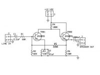
This amp is based around 2n3055 (Siemens) transistor as I have plenty of them in the parts bin.
I wanted to build an amplifier, solid state, as simple as a tube amp.
Design roughly guided by Douglas Self's writings.
I have constructed a crude but operational amplifier but there is a few tiny niggles. The output suffers from "sibilance" like a vinyl record played with a out-of-alignment stylus. Why is that?
Should I exchange the first transistor for a lower current / quiter type?
I call it the "MINIMA SE CLASS A".
Any advice and input highly apperciated.
Dewald
Attachments
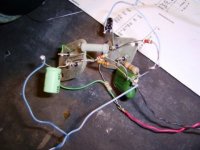
Pic of the working prototype.
Yes, I know the transistors gets hot and must be heatsinked - there is a fan blowing over them whilst I test them. Played for nearly 30 minutes with no trouble.
Powered by a 12v lead acid battery.
Source is a CD-ROM with attenuator.
Load is my set of AKG K240 head monitors.
I am very impressed with the sound but I need to straighten out that sibilance...
D
Attachments
Zen Mod said:base of that left transistor is hungry ;
from where you are feeding it ?
(think about biasing )
Engrish please

D
Zen Mod said:base of that left transistor is hungry ;
Should I change the first 2N3055 to a BC550? Will it work? I'll check tomorrow...
D
GlidingDutchman said:
Engrish please
D
you must add another resistor from positive voltage - to base ;
first transistor isn't biased ;
later you can try smaller input transistors , but first you need to "repair" prototype
")
GlidingDutchman said:
Should I change the first 2N3055 to a BC550? Will it work? I'll check tomorrow...
D
2N3055 = output tube
Now you do not use 6550 as input tube? do you?
More likely an ECC88 or even ECC83
Now 2N3055 needs some current to drive.
So, BC550C may be too weak.
You need more like one MJE340 or BD139.
They are medium power transistors, which usually refers to as 'drivers'.
this is because these transistors have enough current output capacity
to drive big Power tranistors, like 2N3055.
One BC550C is a small signal transistor, which can feed a driver transistor (BD139/MJE340),
which in its turn can drive 2N3055, output.
If you have MOSFET like IRF610 or IRF510,
they can be used as BOTH input and driver.
Nelson Pass has done this. Some times.
Otherwise I say you try first with MJE340 or BD139. They are NPN.
Lineup
regars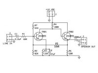
lineup said:
2N3055 = output tube
Now you do not use 6550 as input tube? do you?
More likely an ECC88 or even ECC83
Now 2N3055 needs some current to drive.
So, BC550C may be too weak.
You need more like one MJE340 or BD139.
They are medium power transistors, which usually refers to as 'drivers'.
this is because these transistors have enough current output capacity
to drive big Power tranistors, like 2N3055.
One BC550C is a small signal transistor, which can feed a driver transistor (BD139/MJE340),
which in its turn can drive 2N3055, output.
If you have MOSFET like IRF610 or IRF510,
they can be used as BOTH input and driver.
Nelson Pass has done this. Some times.
Otherwise I say you try first with MJE340 or BD139. They are NPN.
Lineup
Okay... now its becoming a bit clearer...
I have some "exotic" Motorola transistors somwhere and will try them as driver units.
What is your opinion on the biasing of the first transistor?
D
Here they are: http://www.diyaudio.com/forums/showthread.php?s=&threadid=123718
Motorola MJE4919 & SJE5300 transistors
D
Motorola MJE4919 & SJE5300 transistors
D
GlidingDutchman said:Like so (see attachment)
But what will (R7) XXX be?
let flow ,say,2mA trough R7/R2 divider
say that R7/R2 sets base on 3V ( you need amplitude of ,say,4Vpp on input)
R7+R2 = 12V/0,002 = 6K
for 3V across R2 ----- R2= 3V/0,002A = 1k5 ; R7 is rest to 6K
NB - input impedance to your stage will be dominated with value of R2 , and increasing it with R1 will just choke thing or two ;
further:
Vbe voltage is always ~0,65V
so - you'll set current through transistor with R3 ;
say that you want 10mA through that transistor ; so:
R3 = (3V-0,65V)/0,01A = 235E ........... so either 220E or 240E will be fine
that's common logic ; what I didn't encounter is - better input transistor , noise , Hfe etc
try it as I wrote , then play with better input transistor ( weaker , but with greater current gain ........ any smaller TO220 will do) , with current through stages etc .
you'll learn a lot , and understand more what's written in book you already mentioned ; then you'll tweak it further - to achieve better input impedance , broader bandwidth , include feedback , etc .
name of the game is fun
The resistor values in the 1st stage are too high, to make Your amplifier work. R4 can provide about 0.00005mA base current for the output device. This is nothing!
I guess that You have to redesign the first stage. The current must be 100 times higher.
The biasing of the first stage looks OK for me, but You have to increase the base current with about 10 times, for the proper work.
Sajti
I guess that You have to redesign the first stage. The current must be 100 times higher.
The biasing of the first stage looks OK for me, but You have to increase the base current with about 10 times, for the proper work.
Sajti
sajti said:The resistor values in the 1st stage are too high, to make Your amplifier work. R4 can provide about 0.00005mA base current for the output device. This is nothing!
I guess that You have to redesign the first stage. The current must be 100 times higher.
The biasing of the first stage looks OK for me, but You have to increase the base current with about 10 times, for the proper work.
Sajti
Thanks Satji... believe it or not, the sound is rather marvellous that it produces but there is that sibilance (sizzle - probably HF distortion)...
D
I recommend to try some cheap lower power transistors for the first stage, such as BD 139.
Decrease R4 to 1kohm, R3 to 330 ohms, and the bias divider resistors to 22kohm (R5), and 8.2kohm (R2). Lower the input resistor (R1 to 6.8kohm) as well to get the gain (3) as it was before.
I think that some darlington transistor would be much better, as output device. You can increase the bias current with it.
Sajti
D.Self is likely to sue you for comparing your creation to his work.GlidingDutchman said:Design roughly guided by Douglas Self's writings.
Re: Re: Minima SE Class A amplifier - help please
Is that so? He can try as I am flat broke...!
He dont have to stress at all as I have given up on the project. Who am I fooling? I dont know sh!t about amplification design.

D
PS - He also have to find me first... I am in deep DARK africa.... he-he!
AndrewT said:D.Self is likely to sue you for comparing your creation to his work.
Is that so? He can try as I am flat broke...!
He dont have to stress at all as I have given up on the project. Who am I fooling? I dont know sh!t about amplification design.
D
PS - He also have to find me first... I am in deep DARK africa.... he-he!
No Dutch, don't give up - it might be true that your knowledge on this subject is poor, but it shouldn't halt your learning efforts.
Keep learning - it's a sure way to succeed and have fun!
And don't worry about law, no one will sue you about this - Andrew's remark was meant as a joke
Keep learning - it's a sure way to succeed and have fun!
And don't worry about law, no one will sue you about this - Andrew's remark was meant as a joke
http://www.dself.dsl.pipex.com/ampins/discrete/twoq.htm
Hi,
Try the stuff on this page with your (very) basic amplifier.
/sreten.
Hi,
Try the stuff on this page with your (very) basic amplifier.
/sreten.Attachments
Tr decreasing R1 R2 R5 by around 5 times and R3 and R4 by at least 20 times.
next step will be experimenting with a capacitor at TR01 in range of 22p-220pF. Of course this should be small signal transistor, like BC139 as Sajti has said or even something like 2n5551.
Do not give up this project, please
next step will be experimenting with a capacitor at TR01 in range of 22p-220pF. Of course this should be small signal transistor, like BC139 as Sajti has said or even something like 2n5551.
Do not give up this project, please
- Status
- This old topic is closed. If you want to reopen this topic, contact a moderator using the "Report Post" button.
- Home
- Amplifiers
- Solid State
- Minima SE Class A amplifier - help please