The version, which I present now, is very stable and was already tested and compared with several audiophile amplifiers. I'm very pleased with the sound of this amplifier and I hope that you will enjoy as well. ;-)
For sure I'll continue to improve this amplifier and further versions will be published.
For sure I'll continue to improve this amplifier and further versions will be published.
Last edited:
MadMutt said:That's just, well, superb.
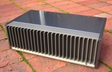
Absolutley stunning metal work.
I'm sure others would love to know what you tried it against, and the results.
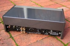
Enclosure is from here.
Regarding comparisons, I'll not give amplifier names because I don't want to start off topic discussions.
IMHO, making an amplifier and stating that this sound very good based on simulations, without any direct comparisons with some high-end gear, is not the right way.
I'm not a spice man. I use spice only to see if some ideas are working or not.
I design, measure, listen and compare, than again design, measure ...
Regards,
Tibi
Great job Tibi ! 
Quad 405 was my high-school project too, and being a same age as you I understand and share your emotions for this amp.
The lack of response in the thread is probably due to output devices you chose - lateral MOSFETs are a bit expensive and not easy to find, +- 60 V PS dictates the use of higher voltage elkos (63 V type is not safe to use here) which are more expensive....
Anyway, you made a great amp which is a bit on the "monster" side where audience is not so big.
Keep up the good work !
Tibi,
Great work, all the way.
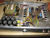
I really like the transformer you are using. Looks like something I saw in a Genelec active studio monitor once.
Also, Thanks for the enclosure link. Good looking and fair pricing.
The enclosure is usually what put my projects on hold.
/ Mattias
Great work, all the way.
I really like the transformer you are using. Looks like something I saw in a Genelec active studio monitor once.
Also, Thanks for the enclosure link. Good looking and fair pricing.
The enclosure is usually what put my projects on hold.
/ Mattias
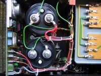
The ugly IRFP version :-D
Here is a picture with one prototipe I used for tests.
This is with vertical mosfets IRFP240/9240.
In this version R3=10Kohm; R10=100ohm; R17=22ohm; R19=220ohm
and only two pairs of IRFP output mosfets.
The sound with IRFP's is very good as well.
Large heatsinks must be used in order to avoid vertical MOSFET run avay.
Regards,
Tibi
Attachments
Leolabs said:Oh vertical fets!Why not normal BJTs???
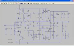
The amplifier is based on a low power A class with T7 & T8 and associated ccs.
This stage need to assure enough gain, in order to have "magic formula" Z1Z3=Z2Z4 working, and also enough current for final stage.
The output impedance, of class A stage, is also quite high at only 50mA.
IMHO to drive BJT's from only 50mA is not enough. At high output levels, a power BJT with a beta of 20-30 will overload class A stage and amplifier will fail into high distortions. I think here more appropriate are Darlington's or Mosfet's.
I didn't managed to get the amplifier stable with Darlington's.
During my tests, I also observed that the amplifier is more stable with very fast output devices. MOSFET's are much faster and this is another reason, beside high input impedance and more easy to drive. I don't want to go into a BJT vs MOSFET debate as long a thread is already discussed here .
As long this is a feed-forward error correction amplifier, another choice are IGBT's, which should work fine as current dumpers and maybe a future version will be with them.
")
Regards,
Tibi
Tibi,
What are D3 and C11 doing in that position?
I expect limitedly magic high distortion in the VAS stage.
I would omit C7 and use polystyrene for C8+C10.
The gate resistor values may be unnecessarily high.
It would have been beneficial to locate high quality film decoupling capacitors close to the output FETs.
Why do you think MOSFETs would do a good job in VAS?
The transformer is extremely nice, Japanese, right?
Lumba Ogir said:Tibi,
What are D3 and C11 doing in that position?
I expect limitedly magic high distortion in the VAS stage.
I would omit C7 and use polystyrene for C8+C10.
The gate resistor values may be unnecessarily high.
It would have been beneficial to locate high quality film decoupling capacitors close to the output FETs.
Why do you think MOSFETs would do a good job in VAS?
The transformer is extremely nice, Japanese, right?
D3 is there in order to provide a decent Vce for T6. Without that diode ccs formed by T5 and T6 will not be a ccs.
I prefer silver-mica for polystyrene especially where inductance may be a problem (C10) and from my tests, silver-mica sound far better than polystyrene.
The gate resistors can be reduced and RC snubbers added for each dumper, but from sonic point of view I prefer large resistors (if possible noninductive).
Yes, some 0,1uF foils near to each output MOSFET is preferable. Here I used Arcotronics polypropylene and this is up to builder and the pcb layout he may use.
Why do you think MOSFETs would do a good job in VAS?
A very good question which need a very complex answer.
The short answer is that I built few low power class A MOSFET amplifiers and they sounded very good.
Do you have any particular reason to believe that a cascoded MOSFET in class A stage will not do a good job ?
Transformer is from SELECTRONIC, but I don't know real producer.
Regards,
Tibi

Originally posted by tvicol
More pictures with finished product. :-D
http://forum.audiofil.ro/index.php?topic=803.0
Regards,
Tibi
Nice boards - do you plan to offer some here?

Tibi,
to me C7, D3 and C11 are muddying parts, an emitter resistor would be much more decent. Cascoding linearizes the VAS and the open-loop, a real magic formula. Concerning suitable devices, dissipation and current requirement complicate things considerably as genuine types for voltage amplification are optimized for low currents, Cob should be very small.
to me C7, D3 and C11 are muddying parts, an emitter resistor would be much more decent. Cascoding linearizes the VAS and the open-loop, a real magic formula. Concerning suitable devices, dissipation and current requirement complicate things considerably as genuine types for voltage amplification are optimized for low currents, Cob should be very small.
QUASAR a QUAD405...
Hi Tibi
Great stuff I bet if I park my original next to your diy and hook up a source and speakers, I would develop a serious case of s/s lust
Here at my house, we recently had a shootout between my 405 which had been given two new caps, two smaller cap replacements on each of the boards, some better binding posts and a coat of left over basecoat/clearcoat.
The other 405 belonging to a friend, had been professionally re-built.
During evaluation with an analogue source, I didn't say anything but my friend got very distressed about how his amp sounded against mine.
The last I heard from him, he had ordered two Kendeil caps and has been bugging the gent who re-built his amp to find the reason for the alleged difference how these amps sounded.
Ouch!
bulgin
Hi Tibi
Great stuff
I bet if I park my original next to your diy and hook up a source and speakers, I would develop a serious case of s/s lust Here at my house, we recently had a shootout between my 405 which had been given two new caps, two smaller cap replacements on each of the boards, some better binding posts and a coat of left over basecoat/clearcoat.
The other 405 belonging to a friend, had been professionally re-built.
During evaluation with an analogue source, I didn't say anything but my friend got very distressed about how his amp sounded against mine.
The last I heard from him, he had ordered two Kendeil caps and has been bugging the gent who re-built his amp to find the reason for the alleged difference how these amps sounded.
Ouch!
bulgin
Attachments
Lumba Ogir said:Tibi,
to me C7, D3 and C11 are muddying parts, an emitter resistor would be much more decent. ...
Lumba,
Thanks for your observations !
My first approach was to use a resistor in that place, but this make things worse. Then I used a cc in that place , this was better, but this generated another problems with power dissipation on the first transistor in the triplet. So far using this solution I got best results.
D3 is biassed to ~50mA and T8 will see his series resistance at high frequency. At low frequency the capacitor C11 will take over.
C7 is there in order to ensure cascode stability at very high frequencies, but I'm looking for an alternative solution with C7 removed.
Regards,
Tibi
Re: Re: QUASAR a QUAD405 reborn design
Yes, I'm currently working with a friend to a version which will accommodate lateral and vertical MOS-FET on the same board.
Regards,
Tibi
dudaindc said:
Nice boards - do you plan to offer some here?
Yes, I'm currently working with a friend to a version which will accommodate lateral and vertical MOS-FET on the same board.
Regards,
Tibi
- Home
- Amplifiers
- Solid State
- QUASAR a reborn design