Hi @ all
i need help to modify my old amp part
from the 80´s .
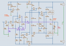
what do you think about the schematic ( its a old Grundig )
Voltage is about 32 V
The electr.caps are changed to panasonic FC types
whats the next stepp ?
Best regards
AMP_Schematic
i need help to modify my old amp part
from the 80´s .
what do you think about the schematic ( its a old Grundig )
Voltage is about 32 V
The electr.caps are changed to panasonic FC types
whats the next stepp ?
Best regards
AMP_Schematic
which boostrap caps & why ?
can you say me the part number on the schematic cxxx?
reducing the resistors to the half value, increase the current
over T401/403 - is this the way .... ?
The Darlington output is already changed to BDV64/65 type.
(they are similar to the special GP-type´s from Grundig)
what the other guys here thinking ?
bye
ECBLN said:
reducing the resistors to the half value, increase the current
over T401/403 - is this the way .... ?
The Darlington output is already changed to BDV64/65 type.
(they are similar to the special GP-type´s from Grundig)
what the other guys here thinking ?
bye
Replacing all electrolytic caps is a good first step.
This means of course the power supply e.caps as well as all smaller polarized e.caps on the amp board.
Like the bootstraps mentioned already.
I hope you have already replaced the input cap (3.3uF) .. with MKT of MKP filmcaps.
A power amplifier is only as strong and as good as its power supply.
In fact, without any power supply, an amplifer is harmless - have no power at ALL!!!
I see after rectification and Unloaded, the supply is supposed to be something like +-30 Volt DC.
-----------
A good guess it is one 2x22 VAC trafo. (they usually gives like 30-33 VDC)
See if you can fit a new toroid trafo.
The output power seems to be 2 x 50 W, at which the voltage drops to 2x 25-26 Volt DC.
If is only one trafo, that is shared (give a theoretical max 100 Watt)
I would buy a 2x22 VAC, 250-300 VA, modern Toroid.
With something like totally 4x10.000 uF Supply electrolyts.
This could make the Power Supply more STIFF.
And voltage wouldnt drop as much at power peaks in music.
-------------------------------
Each amplifier is a system. Transistors and all parts are supposed to work good together.
Changing the wrong Transistor, Resistor or Current is not always better.
Even if a few part is 'modern, stronger & better', the system as a whole may be upset.
And give a less good amplifier.
So, changing one part, and you may have to change several other part, to make them fit good together.
This is why I do not want to suggest my favourite transistors and my own ideas.
-----------------------------
The upgrade of capacitors, to fresh ( not dried out ) exemplars
and changing signal caps, to film types.
And improve the power supply, while keeping orignal intended Voltage.
All these imrovements does not change your amplifier, seen as one designed SYSTEM.
What it does is, it makes the designed system, hopefully, work better.
Lineup
")
sawreyrw said:spind,
The slam (and I don't consider it a slam) came for me, not the original poster. BTW, most of the responses did give any rational. One guy did say it would increase the slew rate, but so what?
Rick
Rick, My mistake. I apologize for reading too fast and jumping to conclusions. My reply was unwarranted.
Steve.
Hi @ all
here are some pics of the amp, its made 1980 ore 1981
its heavy weight amp from Grundig Slim series.
new price in the 80´s about 1000-1500 dollars i think.
i also have the micro controlled fm tuner of this series.
@ line up
as you see is a slimline amp (hight is about 45mm)
all elec.caps are changed to newer ones ( withs less distort.)
the input caps already changed to 3,3uF Wima (mks2 type
cause there is no more place in the cabinet)
the power supply caps and snubbers are changed to 10000µ/50V
(there where orginally Roederstein 6800µ/35V)
the transformer draws about 33-34Volts, and under peak current
its not really less 32 Volts. Its a heavy 220VA type in the middle.
the Amp parts are build as dual mono as you see.
i will post some fotos this weekend with that already modifications.
and will do some measurements.
here are some pics of the amp, its made 1980 ore 1981
its heavy weight amp from Grundig Slim series.
new price in the 80´s about 1000-1500 dollars i think.
i also have the micro controlled fm tuner of this series.
An externally hosted image should be here but it was not working when we last tested it.
An externally hosted image should be here but it was not working when we last tested it.
An externally hosted image should be here but it was not working when we last tested it.
@ line up
as you see is a slimline amp (hight is about 45mm)
all elec.caps are changed to newer ones ( withs less distort.)
the input caps already changed to 3,3uF Wima (mks2 type
cause there is no more place in the cabinet)
the power supply caps and snubbers are changed to 10000µ/50V
(there where orginally Roederstein 6800µ/35V)
the transformer draws about 33-34Volts, and under peak current
its not really less 32 Volts. Its a heavy 220VA type in the middle.
the Amp parts are build as dual mono as you see.
i will post some fotos this weekend with that already modifications.
and will do some measurements.
Hi,
Nice amp. If I were you, I'd be very conservative with mods. Doubling the input stage current will indeed double the slew rate, because the dominant pole is moved to a higher frequency (i.e. closer to the other poles of your circuit), which might compromise the stability of the circuit. Unless you have the means to verify the resulting gain & phase margin after the mod, I'd simply say: don't do it!
Replacing aging electrolytics and other parts that show their age (check those cement resistors and surrounding parts for heat damage) is about all that comes recommended without thoroughly measuring the circuit's actual performance. The amplifier already looks like a very quality conscious build. Replacing parts with other parts that don't fit properly in their alotted space will not exactly enhance reliability, so finding parts that fit might become a challenge.
Anyhow, good luck with it!
Hi @ all
i´will do first measurements with my Emu 1616m
and some loads from 4 to 8 ohm´s.
i can use rmaa proff with asio - so we can see some specs for
different input / output values.
if the results are fine enough , i can measure the amp
with an ATS2 @ work
i already changed the ceramic caps to film, LCR type or
to silver mica
- i hope farnell deliver the last parts @ monday or tuesday
so we can see the results i think next week.
@ lineup
thanks for the sim-file,
ECBLN said:
@ lineup
thanks for the sim-file,
yeah. glad to send it to you.
I am not sure you could run it, though.
I have used my personal models I have added to MultiSim.
Spice modles found on internet and in this forum.
Even the mystical darlingtons in output I had to make myself.
To use as BDV64 BDV65. They are discuontinued and no mdels I found.
I used BD139 + MJ15024, including 2 usual resistors.
And BD140 + MJ15025
I post same schematic here, below.
This is a good amplifier. With very good MultiSim performance.
Upper bandwidth is something like 430 kHz.
It is very well compensated.
Lot's of work done there, of the Grundig developer
I have not done any major changes.
But using 470uF + 470uF in feedback leg, improves Low Bass a great deal.
As well as using 10uF Filmcap input. ( You can parallel two 4.7uF Filmcaps)
Using BC560C input, is also a good thing.
-------------------------------
Well, everybody.
Look for yourself.
And make your own changes .. to try to improve.
Lineup
Attachments
sawreyrw said:I wouldn't change a thing unless you know of a real deficiency. If there's nothing wrong, how will you know the change did any good? Don't just make changes for the sake of change.
I agree, too many times I see people suggesting change after change until the amp has many more components than it needed to work.
I prefer to go for the minimalist approach and if it works well then leave well alone otherwise you are bound to blow something up !
nigelwright7557 said:
I agree, too many times I see people suggesting change after change until the amp has many more components than it needed to work.
I prefer to go for the minimalist approach and if it works well then leave well alone otherwise you are bound to blow something up !
hi,
first thing is, to change the old dry caps to low distortion elect. caps, and the parts that in 80´s was not really up to date ... like the many ceramic caps to film or ps-types... okay its expensive but i have of these slim line amp and expensive fm tuner from Grundig in best condition, the cabinet is like new stock-
the amp sounds really fine .... but some key points can bring
better results in the lower frequency or detaild mids ...
some changes like carbon to metallox. resistors can bring
a brighter room.
so we well see , ...
@ lineup can you take some pics from your simulation data
my sim is not really working please post it - if possible
so guys... i have to go on with my diploma thesis ...
good night
ECBLN said:
@ lineup can you take some pics from your simulation data
my sim is not really working please post it - if possible
so guys... i have to go on with my diploma thesis ...
good night
I did some tests.
At 1 Watt, 25Watt (50% of nominal power) in 8 Ohm. Also at 25 Watt into 4 Ohm.
I found low THD. As I remember it was at the 0.010% level, and below this at 1 Watt.
So if my spice test match your amplifier, I would suppose rather good real life data.
As you noted, I have not included some protection transistors (overload current limiter ..)
and not the inductor + 10 Ohm in series with output.
But I kept the zobel network, 150nF + 10 Ohm.
Because zobel is important to keep from getting oscillation,
if you connect 'the wrong speakers', some time.
Commercial companies can not afford to take any risks with their customers. Will keep them from being objects of legal actions, and keep their products from get bad reputation from some unfortunate user. So they include some standard things to make amplifier 'safe'. To protect even if amplifier should be handled 'badly'.
I will see what images I can produce and post here.
Lineup
lineup said:
This is a good amplifier. With very good MultiSim performance.
Upper bandwidth is something like 430 kHz.
It is very well compensated.
Lot's of work done there, of the Grundig developer
I noticed the 270pf caps on the darlingtons. I know that adds stability, as I've done similar with other amps. IMO it's a great cheap way to avoid oscillation, and I see why Grundig used them.
However, for some reason, some folks will swear up and down that those caps kill the performance.
Well, if over 400khz isn't enough.............. 
BTW, for amp mods, only recommendation I have is to at least double the values of caps in the amp that directly affect the bass. Double the bootstrap caps from 47 to 100uf or more, also double the feedback 47uf cap to 100 or more. It's nice to see a schematic of a real commercial amp, helps give better ideas for DIY amps!
EWorkshop1708 said:
BTW, for amp mods, only recommendation I have is to at least double the values of caps in the amp that directly affect the bass.
Double the bootstrap caps from 47 to 100uf or more,
also double the feedback 47uf cap to 100 or more.
It's nice to see a schematic of a real commercial amp, helps give better ideas for DIY amps!
Yeah, EWorkshop1708
.. i see we have similar ideas about this.
Those that affect the bass are:
----------------------
1. Input cap ( I raised it from original 2.2-3.3 to 9.4 uF, two paralled 4.7uF)
This also shows up in my simulation.
2. Feedback cap ( I raised from original 47uF to 235 uF, two 470uF in series - to make a pseudo-bipolar )
3. Not to forget the importance of: Power Supply
----------------------
Actually it is so, that BASS does not take any more current, than does DISKANT. And so shouldnt teoretically require a more stiff power supply, than the very low audio frequencies.
But with loudspeakers, it is so, that most of them, supposed linear 8 Ohms ( or 4 Ohms ), have dip in impedance, at the low frequencies.
>>> 8 Ohms can go downto ... 5 Ohms
>>> 4 Ohms can go downto ... 2.5-3 Ohms
This means speakers most often are a more heavy load in LOW BASS Region.
Look at Nelson Pass, our heavy power master. His power supply recommendations. It is NOT just because his amplifiers is often Class A. I would say Class AB is maybe even more dependent to a STIFF Transformer / Power Supply, due to the variations in power consumption. ( Class A have same average comsumption, all the time )
This deserves to repeated. Many Times
I usually put it simply like this, and I am not the only one telling so:
... Lineup said:
A power amplifier is only as strong and as good as its power supply.
In fact, without any power supply, an amplifer is harmless
- have no power at ALL!!!
And can do nothing for us. No music
.
I also repeat my first post here, as some may have missed it
Replacing all electrolytic caps is a good first step.
This means of course the power supply e.caps as well as all smaller polarized e.caps on the amp board.
Like the bootstraps mentioned already.
I hope you have already replaced the input cap (3.3uF) .. with MKT of MKP filmcaps.
A power amplifier is only as strong and as good as its power supply.
In fact, without any power supply, an amplifer is harmless - have no power at ALL!!!
I see after rectification and Unloaded, the supply is supposed to be something like +-30 Volt DC.
-----------
A good guess it is one 2x22 VAC trafo. (they usually gives like 30-33 VDC)
See if you can fit a new toroid trafo.
The output power seems to be 2 x 50 W, at which the voltage drops to 2x 25-26 Volt DC.
If is only one trafo, that is shared (give a theoretical max 100 Watt)
I would buy a 2x22 VAC, 250-300 VA, modern Toroid.
With something like totally 4x10.000 uF Supply electrolyts.
This could make the Power Supply more STIFF.
And voltage wouldnt drop as much at power peaks in music.
-------------------------------
Each amplifier is a system. Transistors and all parts are supposed to work good together. Changing the wrong Transistor, Resistor or Current is not always better. Even if a few part is 'modern, stronger & better', the system as a whole may be upset.
And give a less good amplifier.
So, changing one part, and you may have to change several other part, to make them fit good together. This is why I do not want to suggest my favourite transistors and my own ideas.
-----------------------------
The upgrade of capacitors, to fresh ( not dried out ) exemplars
and changing signal caps, to film types. And improve the power supply, while keeping orignal intended Voltage.
All these imrovements does not change your amplifier, seen as one designed SYSTEM.
What it does is, it makes the designed system, hopefully, work better.
Lineup
hi lineup,
the value on the spec is in the 80´s for 220Volts.
they were calculated like the earlier din norms
for example for full power @ 205 V or 210 Volts.
And the Grundig engineers did a fine job with that
amp.
with actual line voltage (i measured 230V)
the transformer performs with no load ~ 23,95 V AC, after rectifier 33,56V DC . (no load means signal to ground, ~ 80 mA bias current each channel; each amp has its own rectifier + 2* 10000uF/50V caps)
i think - for these 2 mono amps the transformer its stiff enough.
It is very huge for a slim line amp with 16*13*4,3cm type, heavy weight with dampers on the connection points to the in frame cabinet.
next week or so, i can measure under full load , and under practical conditions, with no changes on the cap values (only changing to newer types).
i think it can draw about 65 -70 W RMS into 4 R load with no clipping.
and about 45-55 W into 8 R load. ( its really enough for a slim line with only one pair Darlingtons like the BDV64/65/ with 2 pairs of that fine soundig darlingtons you can get easily about 120 RMS into 4R)
in the 80´s Grundig made very fine amps - see the Grundig A5000
series or the SXV 6000 preamp (slim height).
where are the other DiyAudio Analog Guru´s ?
- Status
- This old topic is closed. If you want to reopen this topic, contact a moderator using the "Report Post" button.
- Home
- Amplifiers
- Solid State
- modify my old 80s amp