Hi
Just connect the five diodes in series and place them instead of the zener like the constant current source on the same schematic... but look at the polarities of the diodes...
About stability, didn’t had any problems with this particular amplifier... in your case what I would do (and did") )is to bandwidth limit the output stage because you are going to use fast transistors, RC network in front of the drivers will do the trick. A 100ohm resistor (if you look the resistor is already there) and a 100pf cap conected between the base of the transistor and the power rail.
)is to bandwidth limit the output stage because you are going to use fast transistors, RC network in front of the drivers will do the trick. A 100ohm resistor (if you look the resistor is already there) and a 100pf cap conected between the base of the transistor and the power rail.
If stability is ok on resistive load, connect a crapy loudspeaker and see what happens (nothing like a real test load )
One more time I say, oscilloscope is mandatory!!!!!
About output transistors placing... as I was modifying a commercial unit, I made an aluminum U that is attached to the heat sink and I put there the TO3 devices and connected them to the board with wires(if you are going to do that, keep your wire short...) and connected the vbe transistor to the U.
Best regards
Rcardo
Just connect the five diodes in series and place them instead of the zener like the constant current source on the same schematic... but look at the polarities of the diodes...
About stability, didn’t had any problems with this particular amplifier... in your case what I would do (and did
)is to bandwidth limit the output stage because you are going to use fast transistors, RC network in front of the drivers will do the trick. A 100ohm resistor (if you look the resistor is already there) and a 100pf cap conected between the base of the transistor and the power rail.If stability is ok on resistive load, connect a crapy loudspeaker and see what happens (nothing like a real test load
)One more time I say, oscilloscope is mandatory!!!!!
About output transistors placing... as I was modifying a commercial unit, I made an aluminum U that is attached to the heat sink and I put there the TO3 devices and connected them to the board with wires(if you are going to do that, keep your wire short...) and connected the vbe transistor to the U.
Best regards
Rcardo
OH Yeah!
Speaking of resistive loads.... I read on Anthony Holtons site that he connects a resistive load instead of the final output FET's so he can check for problems and set the bias current to an initial setting. I suppose this helps the builder to not blow up the final stage if they set the bias pot wrong. Can it be done here also? Did you use a 3/4 turn pot or a 10 turn pot for the bias adjustment pot?
Diodes..... Is the polarity the same as the zener in the original circuit? Again, the resistor needed right? Does it need to change value as the regulating diodes are different?
Thanks again for the continued information!!!
Chris
Hi Chris
When I connect an amplifier I normally don’t use a load on the output stage as you already have one there... the zobel!
But you can use a resistor if you like. If you use a loudspeaker, and you have an offset problem you kill the loudspeaker
On the power up I always put a power resistor in series with the power rails to limit the current in case something goes wrong
15ohm 10watt power resistor will do the trick
Adjusting the bias... just set the pot to maximum position.
I always use multiturn pots. They are much better and easier to adjust.
About the diodes... imagine five zeners in series the polarity is reversed. it's all you need to do. Keep the 11k resistor as it is.
Best regards
Ricardo
When I connect an amplifier I normally don’t use a load on the output stage as you already have one there... the zobel!
But you can use a resistor if you like. If you use a loudspeaker, and you have an offset problem you kill the loudspeaker
On the power up I always put a power resistor in series with the power rails to limit the current in case something goes wrong
15ohm 10watt power resistor will do the trick
Adjusting the bias... just set the pot to maximum position.
I always use multiturn pots. They are much better and easier to adjust.
About the diodes... imagine five zeners in series
the polarity is reversed. it's all you need to do. Keep the 11k resistor as it is.Best regards
Ricardo
Banned
Joined 2002
www.aussieamplifiers.com.
it is weird he never updates his pages or emails yu back any more.
damit. : O (
it is weird he never updates his pages or emails yu back any more.
damit. : O (
Thanks Ricardo!
OK, I put 5 1N4148 diodes in series, treat them as they were 1 zener, and keep the polarity the same as the zener in the diagram? This may sound a bit tiring but you know the consequences if a mistake is made! BOOM!
Also you say to put a 100Pf cap on each base of the outputs to its corresponding rail, right? Do I do this with the drivers too?
I'm being so detailed as I'm just about finished with a reasonable layout and I'm about to start buying parts. I'd like to get it right the first time!!!!!!!
You said to set the bias pot to set the pot to the maximum position. Can you tell me which side to set it to. I look at the diagram and it is between 2 parts or easier said, in the diagram, do I set ot "up towards the 100 ohm resistor" or "down where the 2 poles of the pot are tied together?"
Again, thanks for your help!
Chris
Hey Jason,
Yup, that's the problem. Now, do you think that I'm going to trust him with my money? I don't think so........ If he won't answer inquiries about his projects, why should I think that he will send me his PC boards? OK, I'm finished being rude.
The other problem is a suitable place to buy FET's. I have chosen this project and will stick with it. I'm pretty excited about it and will post my stuff and changes to the circuit when finished if someone wants it.
Chris
400W enough?
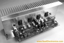
Randy Slone is offering a 400watt version of his amp in a kit on his web site. It is a very durable versatile design. Here is a pic with the website. The great part is his kits are complete, just add the rest of your case and PSU(which you can get from him if you want)
Randy Slone is offering a 400watt version of his amp in a kit on his web site. It is a very durable versatile design. Here is a pic with the website. The great part is his kits are complete, just add the rest of your case and PSU(which you can get from him if you want)
Attachments
Hi Chris
A diode is forward biased device and a zener is a reversed biased device, so you will have to reverse the diodes in relation to the zener on the circuit. Sorry I wasn’t very explicit on my last post regarding this subject.
I you put the resistors on the power rail's like I said earlier you wont have a boom!!! Just some very hot resistors!
The pot is wired like a variable resistor. So at maximum (maximum position is down where the 2 poles of the pot are tied together) it will have 200ohms, at minimum it will have 0 ohms. Measure the pot on the circuit with a multimeter just to be sure.
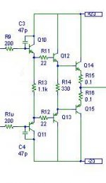
About the bandwidth limit cap, I’m going to attach a picture that I hope it will clarify some things look at the RC filters on that output stage.
Glad I can help you, I will try to answer your questions as best as I can
Best regards
Ricardo
A diode is forward biased device and a zener is a reversed biased device, so you will have to reverse the diodes in relation to the zener on the circuit. Sorry I wasn’t very explicit on my last post regarding this subject.
I you put the resistors on the power rail's like I said earlier you wont have a boom!!!
Just some very hot resistors!The pot is wired like a variable resistor. So at maximum (maximum position is down where the 2 poles of the pot are tied together) it will have 200ohms, at minimum it will have 0 ohms. Measure the pot on the circuit with a multimeter just to be sure.
About the bandwidth limit cap, I’m going to attach a picture that I hope it will clarify some things
look at the RC filters on that output stage.Glad I can help you, I will try to answer your questions as best as I can
Best regards
Ricardo
Hey Ricardo,
In the previous post, you said that the capacitor went between the base and the rail...... Did you do it only on the drivers or on each output transistors as well? I really appreciate all of the support! I used to make Native American (Indian) flutes and I belong to different forums and help others with my other passion. I really like to hear when I tell someone something and they do it and are successful in making their own flutes. Anyway.........
I understand the picture!
As always, Thank you very much...
Chris
Hey Philo,
Thanks for the web site.... I will look them up. I have built 7 kits that deliver 366W into 4 Ohms. I want to build one from scratch this time. I use the others in my home theater and really like them so far. I have been using a Crown CE-1000 for my subs but the input of pro audio needs to be a lot higher than home stuff and I haven't built a pre-amp to do that yet so my subs are weak. I want to build an amp from scratch and if it does well, I'll build 2 and use them for my subs. My subs are Shiva's and are a bit power hungry. Great sub though!!! Yes, my Crown can handle that but I have another use for it anyway.
Chris
Hi Chris
The output I use is a triple follower. Exactly equal like the one on the picture with different resistor values, so just one RC on front of the first driver. By the way the one on the picture will work without any modification
And try this amplifier on your main system; maybe it’s better than your kit amplifier. I think you will like it
about Randy Sloane amp, I don’t like it for the same reason I have mentioned before about the AV800 and it uses the very expensive double die mosfet by semelab. I think the one you are doing with the mods, has better performance and you will learn a lot more doing a design from scratch than doing a kit: cool:
Good luck for your project
Best regards
Ricardo
Ricardo,
Your right about the learning process, doing it from scratch is the best to really learn about amp design, but sometimes the hard way. No offense, I just posted Randy's website because of the earlier remarks and he stands behind his designs and products faithfully and will write you back if you have trouble. After building a few older, mod'ed designs, I got tired of doing endless part searches (although, I am back doing it now for some Alephs) it was nice change to build from a kit that already had matched transitors and the gain values were hashed out. I am not sure of what terms you are speaking about when you say "better performance", though.
Your right about the learning process, doing it from scratch is the best to really learn about amp design, but sometimes the hard way. No offense, I just posted Randy's website because of the earlier remarks and he stands behind his designs and products faithfully and will write you back if you have trouble. After building a few older, mod'ed designs, I got tired of doing endless part searches (although, I am back doing it now for some Alephs) it was nice change to build from a kit that already had matched transitors and the gain values were hashed out. I am not sure of what terms you are speaking about when you say "better performance", though.
Hi Philo
I agree whit your post, I was just talking about the design of that particular amp on the pic you posted I even have a book by Randy Sloane
About performance...
Again I say that I don’t think that driving mosfet whit high source impedance is a good design practice...
The output impedance of the vas stage (a cascode vas will be even worse for obvious reasons) with the capacitance of the mosfet will form a very big RC filter and you will end with a very slow and non linear output stage. and in the end, a slow amplifier. Not my cup of tea
Best regards
Ricardo
I agree whit your post, I was just talking about the design of that particular amp on the pic you posted
I even have a book by Randy SloaneAbout performance...
Again I say that I don’t think that driving mosfet whit high source impedance is a good design practice...
The output impedance of the vas stage (a cascode vas will be even worse for obvious reasons) with the capacitance of the mosfet will form a very big RC filter and you will end with a very slow and non linear output stage. and in the end, a slow amplifier. Not my cup of tea
Best regards
Ricardo
That's what I thought you meant. I agree about the sound but it not always true, keep your capacitance matching on the low side seems to help as well as using some very small bypassing caps. As you mentioned before you have to watch your stability. Judging by Chris's other equipment he has an affinity to the pro-sound and "performance" usually translates to durability and sustained raw power.
and "performance" usually translates to durability and sustained raw power.Judging by Chris's other equipment he has an affinity to the pro-sound and "performance" usually translates to durability and sustained raw power.
Yes, performance is key. I am NOT into PA systems and the like. Actually, I bought the Crown amplifier as a last resort because I couldn't find an affordable, high power, good sounding subwoofer. I was ignorant to the input requirements of "pro audio" Those amps need a lot more PK-PK signal to drive them well. Home audio is much more sensetive and can amplify small signals better. My other amps were kits and I got them on a clearance sale. They weren't designed with adequate heat sinking OR output devices. They could stand at least 2 more output devices per rail and a honking big heatsink. The power transformers are a bit under rated. Since I never use their full power output, they run just fine and sound good as well. The rails are supposed to be +/- 75VDC @ 8A but are hardly that. At full power, the rial voltage drops to 68V. With only 2 2N3773 output devices per rail, well, I only get 244W RMS into 8 Ohms. I get 366W RMS into 4 Ohms but the heatsinks get hot enough to fry eggs with. TOOOO hot!!!!! They suggest a fan to cool it with but I'm fresh out of Hurricanes! LOL My thinking and experience about a lot of power. I have always heard high power amps with good speakers and the detail is wonderful and if it needs to go loud and clear, ie. a big transient, it can and still be very clear and responsive. Car audio, for example, I have never heard a good subwoofer, that was clean and extremely responsive, that had a low power amp. They ALWAYS have a huge amp and a lot of headroom. I know that the drivers have a lot to do with it as well but you can see my concept here. Well, I bought my subs and they are called Shiva subwoofers. They can take a lot of power so I don't overdrive the driver or amplifier. Those 2 things, in my book, equal clean, responsive sound.
Chris
Yes, performance is key. I am NOT into PA systems and the like. Actually, I bought the Crown amplifier as a last resort because I couldn't find an affordable, high power, good sounding subwoofer. I was ignorant to the input requirements of "pro audio" Those amps need a lot more PK-PK signal to drive them well. Home audio is much more sensetive and can amplify small signals better. My other amps were kits and I got them on a clearance sale. They weren't designed with adequate heat sinking OR output devices. They could stand at least 2 more output devices per rail and a honking big heatsink. The power transformers are a bit under rated. Since I never use their full power output, they run just fine and sound good as well. The rails are supposed to be +/- 75VDC @ 8A but are hardly that. At full power, the rial voltage drops to 68V.
With only 2 2N3773 output devices per rail, well, I only get 244W RMS into 8 Ohms. I get 366W RMS into 4 Ohms but the heatsinks get hot enough to fry eggs with. TOOOO hot!!!!! They suggest a fan to cool it with but I'm fresh out of Hurricanes! LOL My thinking and experience about a lot of power. I have always heard high power amps with good speakers and the detail is wonderful and if it needs to go loud and clear, ie. a big transient, it can and still be very clear and responsive. Car audio, for example, I have never heard a good subwoofer, that was clean and extremely responsive, that had a low power amp. They ALWAYS have a huge amp and a lot of headroom. I know that the drivers have a lot to do with it as well but you can see my concept here. Well, I bought my subs and they are called Shiva subwoofers. They can take a lot of power so I don't overdrive the driver or amplifier. Those 2 things, in my book, equal clean, responsive sound.Chris
- Status
- This old topic is closed. If you want to reopen this topic, contact a moderator using the "Report Post" button.
- Home
- Amplifiers
- Solid State
- 500W amp