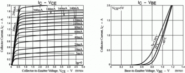
I can't seem to figure what this thing is or how it works.
There seems to be Wikipedia entry, but only in Korean
at the moment... Patent 6545341 does seem to be in
English, yet all but indecipherable.
There is a Sanyo Part# GK001T, gives enough specs to
decide it might be useful if I understood it better, but
does nothing to explain how it really works!
I don't even know if there is a unique schematic symbol
yet for this type of device! The DUT schematic shows the
same symbol as an ordinary BJT...
Most curves are given at regular 20ma spacings, all except
5, 10, and 250ma tacked on at random interval just to make
it look strangely non-linear to the first casual glance....
I do not believe that to be the actual case.
The transfer function seems smooth, but unlike almost any
other device, get curves bunch closer together at the top
instead of the bottom.
WTF??? Anyone ever use these?
Attachments
unclejed613 said:i don't know if it looks any good for audio outputs. it shows severe beta droop in the Hfe/Ic curve going from over 1000 at low collector currents, down to 10 at 2A. that's two orders of magnitude!!!!! i think that's why it's listed as a switching transistor.
Because the compression is on the top end of the load line
where it probably belongs anyway, it can't sound good?
Somehow that logic just don't make sense....
Everything these days is listed as a switching transistor.
Its all about what sells volume, not what else it can do.
it looks very linear up to 100mA, so it would make an o.k. driver, but the nonlinearity in the upper end would definitely distort. it might help with crossover distortion, but would introduce distortion at the peaks. it would also nonlinearly load the VAS or drivers. this isn't a case of beta falling off from 100 to 50 along the Ic curve, this is beta falling off from 1000 to 10.
Yes, and your point is?
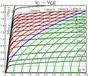
Anyways, I was screwin around what else this "inverted" compression
(probably easier to use for compression than the "normal" way) might
be useful for...
I been looking into FETron / Schade 1938 beam triode emulation.
Wondered what would happen if????
Yup, looks like we may have here a standalone Antitriode emu!
(Read MJK, SmokingAmp, Wavebourne, and my Anti-Triode posts
over in Tubes) Its a virtual device for SEPP applications.
Attachments
Almost fooled myself to thinking I had Gyrated the virtual Triode
rather than creating an Anti-Compliment. Yet when I look for the
axis of constant Mu, I can see that axis is still horizontal... Wierd
as it looks, I think this is the correct behavior I was shooting for.
Just one way to abuse a new device, I'm sure there are others...
rather than creating an Anti-Compliment. Yet when I look for the
axis of constant Mu, I can see that axis is still horizontal... Wierd
as it looks, I think this is the correct behavior I was shooting for.
Just one way to abuse a new device, I'm sure there are others...
- Status
- This old topic is closed. If you want to reopen this topic, contact a moderator using the "Report Post" button.
- Home
- Amplifiers
- Solid State
- GTBT (Grounded-Trench-MOS assisted Bipolar-mode Field Effect Transistor)???


