There are single-ended versions...
TLOxx datasheets show us... an input opamp, and an opamp at each output.....
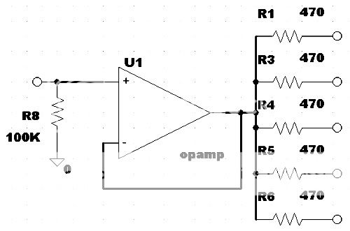
(hey, why is that first opamp inverted?)
...or there's the input opamp, with a single buffer and distributed via 'build-out' resistors....
http://www.diyaudio.com/forums/showthread.php?postid=197930#post197930
(thanks/credit to PRR)
Balanced versions of these.......
The first schematic is similar to the Audio Metrics DA16:
http://www.radiosystems.com/Manuals/da8-16manual.pdf
...and in the Sigma Electronics ADA-106, or some Leitch models, that buffer the differential signal, then employ build-out resistors at the outputs. (no schem available.)
The first balanced version converts the balanced input(s) to single ended....then distribute.....then re-balance the outputs.
Is there a way to keep the entire process balanced all the way through?
Is there a reason it is not done this way?
Is it because it is too difficult to keep the differential signal matched (cmr?) , especially when adding a level control?
As you might guess, I'd like to build a high quality balanced DA.
If there were to be the "ultimate" overkill DA, how would it be done ?
But in real-world "do-able" DIY terms (using IC opamps)....how ?
=RR=
TLOxx datasheets show us... an input opamp, and an opamp at each output.....
(hey, why is that first opamp inverted?)
...or there's the input opamp, with a single buffer and distributed via 'build-out' resistors....
http://www.diyaudio.com/forums/showthread.php?postid=197930#post197930
(thanks/credit to PRR)
Balanced versions of these.......
The first schematic is similar to the Audio Metrics DA16:
http://www.radiosystems.com/Manuals/da8-16manual.pdf
...and in the Sigma Electronics ADA-106, or some Leitch models, that buffer the differential signal, then employ build-out resistors at the outputs. (no schem available.)
The first balanced version converts the balanced input(s) to single ended....then distribute.....then re-balance the outputs.
Is there a way to keep the entire process balanced all the way through?
Is there a reason it is not done this way?
Is it because it is too difficult to keep the differential signal matched (cmr?) , especially when adding a level control?
As you might guess, I'd like to build a high quality balanced DA.
If there were to be the "ultimate" overkill DA, how would it be done ?
But in real-world "do-able" DIY terms (using IC opamps)....how ?
=RR=
Redrabbit, the first op amp is inverting because the person that drew it made a mistake and transposed the inputs. Inverting should be on top and non inverting below. As shown, the amplifier has positive feedback and would thus make a better oscillator than an amplifier!
As for maintaining balanced throughout, implementing gain controls would be a bit more difficult and I don't believe you gain anything performance wise. If you are seriously interested in a balanced system have a look at www.thatcorp.com. The "outsmarts" line driver and "ingeneous" line receiver look set to become the standard for proffessional use.
Keith
The usual suspects among audio professionals come from Analog Devices and Texas Instruments, although THAT outperforms them (for a considerably higher price).
My experience also is that going balanced all the way through a device is not beneficial unless you go overboard with capacitor and resistor selection, potentiometer accuracy, board layout and wiring. Having a balanced input receiver and a balanced output transmitter is all that is required in order to interface complex electronic devices to each other.
OTOH, going symmetric all the way can be benefical in digital interfacing systems, where i.e. only the input stage before an ADC and the post filter stage after a DAC are analogue opamp circuitry! In these special cases, the circuit complexity is usually low enough to justify higher quality symmetric component selection, as the parts count is usually reasonably low.
If you're talking about symmetric transducer preamps, passive line stages, Pass amps and transformer driven electro- or magnetostats, that's another story. But in that case an opamp interface would be out of question anyways, I suppose...")
Cheers,
Sebastian.
My experience also is that going balanced all the way through a device is not beneficial unless you go overboard with capacitor and resistor selection, potentiometer accuracy, board layout and wiring. Having a balanced input receiver and a balanced output transmitter is all that is required in order to interface complex electronic devices to each other.
OTOH, going symmetric all the way can be benefical in digital interfacing systems, where i.e. only the input stage before an ADC and the post filter stage after a DAC are analogue opamp circuitry! In these special cases, the circuit complexity is usually low enough to justify higher quality symmetric component selection, as the parts count is usually reasonably low.
If you're talking about symmetric transducer preamps, passive line stages, Pass amps and transformer driven electro- or magnetostats, that's another story. But in that case an opamp interface would be out of question anyways, I suppose...
Cheers,
Sebastian.
redrabbit said:
Balanced versions of these.......
The first schematic is similar to the Audio Metrics DA16:
http://www.radiosystems.com/Manuals/da8-16manual.pdf
As you might guess, I'd like to build a high quality balanced DA.
If there were to be the "ultimate" overkill DA,
how would it be done ?
But in real-world "do-able" DIY terms (using IC opamps)....how ?
.
Hello.
To make a good balanced driver, Output .. is not as easy, as we may think.
Same goes for making a good balanced Input stage.
Certainly not just take
- one non-inverted and
- one inverted Opamp, for output
Yeah, okay
we can do it, if we do not care to much about true Precision and low distortion.In fact, I would prefer 99 times out of 100 to use
un-balanced signal like normal
before a badly tracking, not very well matched
balanced signal input
There are such really high quality IC-s for professional Audio use.
By Analog Devices.
They are easy to use, and are TRULY matched to 'the last drop' !!!!
Also, they do not cost more, than we can afford to buy them.
It should not be too difficult to find a dealer close to you.
Building my own homemade Balanced driver + Receiver + Amplifier
is something I would NOT want to do.
If I wanted this and really needed, I would go for some dedicated IC, like the ones by Analog Devices.
Audio Regards
lineup
====================
Recommended:
An externally hosted image should be here but it was not working when we last tested it.
Analog Devices, AD
SSM2141 High Common-Mode Rejection Differential Line Receiver
http://www.analog.com/en/prod/0,2877,SSM2141,00.html
An externally hosted image should be here but it was not working when we last tested it.
And just for the sake of completeness, there's also the DRV134 transmitter and INA134 receiver from Texas Instruments, as TI claims them to be an improvement over the AD devices.
Those four ICs (in general) are also used in many projects here on diyaudio.com, just do a search for the part numbers.
The THAT ICs would still be better and - in the sense of lineup's explanation - also be among the parts a DIYer could afford for the occasional project. They are just a tad little more difficult to source for many of us.
Cheers,
Sebastian.
PS @lineup: "point of view"
sek said:And just for the sake of completeness, there's also the DRV134 transmitter and INA134 receiver from Texas Instruments, as TI claims them to be an improvement over the AD devices.
Those four ICs (in general) are also used in many projects here on diyaudio.com, just do a search for the part numbers.
The THAT ICs would still be better and - in the sense of lineup's explanation - also be among the parts a DIYer could afford for the occasional project. They are just a tad little more difficult to source for many of us.
Cheers,
Sebastian.
PS @lineup: "point of view"
Thanks, sek, Sebastian.
I will remember the good Texas alternatives.
Just if anyone asks again.
Personally, I have never had the need to go balanced, ever.
Regards
lineup
still, today, a reasonably Balanced man Redrabbit, I had a couple of thoughts after posting above. The problem with a fully symetrical (balanced) system is that if you disturb the balance of one of the outputs you are likely to do the same to all the others for any conceivable topology that comes to mind. Also note that the THAT CORP line driver chips and possibly others, need to be fed from a low source impedance (less than 500 ohms) This tends to put the kibosh on a normal gain control pot between the two stages. I find it hard to imagine why you would want gain controls on a distribution amplifier when its main function is to take a signal and split it N ways, preferably unaltered.
Keith
Keith
Thanks for the replies everyone.
I have used the balancing chips before (INA, SSM, THAT) . Strange though, the balanced drivers are always in more demand.......digikey is often out of them.
The reason for my quest to build a DA is.... firstly: to learn something..... secondly: to customize it to my needs..... thirdly, to pet my ego. (NNITO)
I have plenty of receivers SSM2143, INA2137.....but I'm out of the THAT 1646 drivers at the moment.
I do enjoy the challenge of building perfectly symmetrical 3 chip instrumentation amps, or line drivers, I won't enjoy building 12 of them.
You're right Keith, THAT1646 datasheet says:
So another buffer opamp before each might be necessary.
QUESTIONS.....
If I went with these chips and I wanted gain (level) adjustment, I assume I'd wire the receivers , for +2 gain (as stated in the datasheets)...and add a (trim) pot before the balancing output chip ?
Also, what about the DA method I described in my OP....about the circuit that drives one balanced, current boosted output, then uses build-out resistors ?
I assume this consists of one receiver, and one driver with a power buffer on it's output (discrete buffer, of packaged -BUF634) with a single gain control (??)
http://i5.photobucket.com/albums/y177/Midiot/DSCN3358.jpg
http://i5.photobucket.com/albums/y177/Midiot/DSCN3359.jpg
Perhaps I'll do up a rough schematic of either version.
=RR=
I have used the balancing chips before (INA, SSM, THAT) . Strange though, the balanced drivers are always in more demand.......digikey is often out of them.
The reason for my quest to build a DA is.... firstly: to learn something..... secondly: to customize it to my needs..... thirdly, to pet my ego. (NNITO)
I have plenty of receivers SSM2143, INA2137.....but I'm out of the THAT 1646 drivers at the moment.
I do enjoy the challenge of building perfectly symmetrical 3 chip instrumentation amps, or line drivers, I won't enjoy building 12 of them.
You're right Keith, THAT1646 datasheet says:
devices must
be driven from a low-impedance source, preferably
directly from opamp outputs, to maintain the
specified performance.
So another buffer opamp before each might be necessary.
QUESTIONS.....
If I went with these chips and I wanted gain (level) adjustment, I assume I'd wire the receivers , for +2 gain (as stated in the datasheets)...and add a (trim) pot before the balancing output chip ?
Also, what about the DA method I described in my OP....about the circuit that drives one balanced, current boosted output, then uses build-out resistors ?
I assume this consists of one receiver, and one driver with a power buffer on it's output (discrete buffer, of packaged -BUF634) with a single gain control (??)
http://i5.photobucket.com/albums/y177/Midiot/DSCN3358.jpg
http://i5.photobucket.com/albums/y177/Midiot/DSCN3359.jpg
Perhaps I'll do up a rough schematic of either version.
=RR=
By +2 gain you presumably mean x2 gain which is 6bB. If you were to cascade this stage with a balanced driver which also has 6 dB gain (single ended to differential) you will end up with 12 dB gain overall. I would be inclined to use the line receivers with -6dB gain to give a system gain of unity.
A buffer with build out resistors is another approach to achieving a splitting function. This is a common method used in VDA's (video distribution amps). Each output has a 75 ohm source impedance defining resistor to give minimal reflections when used with 75 0hm coax cable. The low driving source impedance in the amplifier results in good isolation between outputs. In audio we do not concern ourselves with reflections so the build out resistors will be given a value for different reasons including, do we want the system to tolerate shorted outputs? how many?. How long, and therefore what capacitance are the cables going to have? Apart from any of the foregoing the resistors will be needed to preserve the stability of the driving amp when loaded with cable capacitance. For a given cable capacitance per metre the source impedance has a big effect on high frequency losses. There is a Rane Corp tutorial on this subject.
Keith
Hi,
when terminated coax is used to feed the buffered audio signal to the next stage, what impedance does the buffer see at it's output?
Is it the 75r series resistor at the buffer + 75r load resistor to ground at the far end of the 75ohm coax?
At audio frequencies does the cable have no effect on this total 150r load?
AndrewT, you are correct in that for a single load on the buffer stage described the amp would be seeing 150 ohms. You need to generate a signal of twice the voltage you want as half of it is lost in the source impedance defining resistor and the other half arrives at the far end of the cable. The source resistor is called a back terminating resistor I think. This type of system results in a high "return loss" both for forward and reflected signals. This type of system with matched source/cable/load impedances has very limited application in audio outside of telecommunications.
In the real world of audio, reflections due to what ever cause are going to arrive back at the source much sooner than the period of the highest frequency signals and thus can be ignored. This reality is why source impedances tend to be low and load impedances high and the cable characteristic impedance does not matter. It goes by the name of "voltage matching" and has been in use for 30 odd years.
Keith
From today's TI newsletter...
DRV601
"DirectPath™ Stereo Line Driver with Variable Input Gain: The DRV601 is a cost-effective, integrated stereo audio line driver designed to drive 600Ù or high-line impedances. An integrated charge pump enables operation from a single external supply voltage and the device allows input gain to be set by external resistors.
SNR: 109dB
2VRMS/Ch output voltage into 600Ù at 3.3-V supply
Applications: Set-top boxes, CD/DVD players, DVD receivers, HTIB, PDP/LCD TVs
DRV601 Price (1ku): $0.75"
Andrew, you must have been at your computer when I posted! Yes all cables will have capacitance which will be in parallel with the load. It is not the value of the capacitance alone that counts but the value in relation to the source impedance of the generator (the device driving the cable). With these two elements we have a low pass filter. This is explained in the Rane notes mentioned above.
Keith
Keith
Redrabbit, if you are still following this thread there is a thread on a forum at http://picocompressorforum.com/forum/php/viewtopic.php?=7&t=123 dealing with this exact topic. Maybe it's another incarnation of you? Cheers
Keith
Keith
Keith Taylor said:Maybe it's another incarnation of you? Cheers
Keith
Yes, that's my other ego.
I went over there because I knew they (mediatechnology, etc) have a lot of experience with the "THAT" audio products.
Anyone wishing to see my block diagram/schematic should visit the link Keith gave above.
I've already built it, so far, so good. Very simple. Testing it this week.
=RR=
Redrabbit, the first op amp is inverting because the person that drew it made a mistake and transposed the inputs
Correct. Based on the typography it looks like it came from TI. They probably ought to fix that one.
mediatechnology said:
Correct. Based on the typography it looks like it came from TI. They probably ought to fix that one.
(sarcastic giggle)...As far back as 1999 (or longer??) this mistake has been present. The current TL08x datasheet still wrong.
http://focus.ti.com/lit/ds/symlink/tl081.pdf
But the TL07x has it correct (shows the same circuit application).
Datasheets too often have mistakes. I don't think they pass thru the lab for approval.
Can you find a mistake in this Analog Devices schematic?
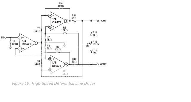
=RR=
- Status
- This old topic is closed. If you want to reopen this topic, contact a moderator using the "Report Post" button.
- Home
- Amplifiers
- Solid State
- Audio Distribution - balanced