OK... I tried to attach an image.. but its in emf? format.
Simply put... the pre-amp was simulated with 2N3819's and BC547's.
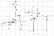
It has a cascode 2N3819 with a 560 ohm source resistor and a 10K drain resistor.
Running from a +36v supply... that places the upper 2N3819 drain at around 18v.
This is taken from this point into 3 paralleled BC547 emitter followers with a common 270 ohm resistor.
Output is taken from this point via a 1uf cap and a 10K load resistor.
Simulating the circuit... I get 0.0001% THD with 10v peak output at 1Khz.... but at 10Khz get 3.53% THD...
Why the huge difference?
Should I be running more current in the cascode?
btw... I need a voltage gain of 10.
Thanks!!!!
Simply put... the pre-amp was simulated with 2N3819's and BC547's.
It has a cascode 2N3819 with a 560 ohm source resistor and a 10K drain resistor.
Running from a +36v supply... that places the upper 2N3819 drain at around 18v.
This is taken from this point into 3 paralleled BC547 emitter followers with a common 270 ohm resistor.
Output is taken from this point via a 1uf cap and a 10K load resistor.
Simulating the circuit... I get 0.0001% THD with 10v peak output at 1Khz.... but at 10Khz get 3.53% THD...
Why the huge difference?
Should I be running more current in the cascode?
btw... I need a voltage gain of 10.
Thanks!!!!
Simulations
Hi Richard
First of all it would help with a schmatic
The THD simulation is difficult, since it's based on samples, and a FFT (Fast fourier transform) The problem is problably the simulator and not your amp.")
Also the THD needs a center freq to do the calculations. What program do you use?
My experience is that simulations are less than perfect regarding THD, but a nice tool to make sure all your DC levels are right.
\Jens
Hi Richard
First of all it would help with a schmatic
The THD simulation is difficult, since it's based on samples, and a FFT (Fast fourier transform) The problem is problably the simulator and not your amp.
Also the THD needs a center freq to do the calculations. What program do you use?
My experience is that simulations are less than perfect regarding THD, but a nice tool to make sure all your DC levels are right.
\Jens
split supply
oh... well since the source of the FETS are about 1v above ground.
And btw I changed the drain resistor to 12K and the source to 680. Better symmetrical clipping...
I would have to go with a split supply to build a CCS for the source of the input FETS.
I could try a CCS on the output NPN....
oh... well since the source of the FETS are about 1v above ground.
And btw I changed the drain resistor to 12K and the source to 680. Better symmetrical clipping...
I would have to go with a split supply to build a CCS for the source of the input FETS.
I could try a CCS on the output NPN....
THD figures
Run a transient analysis... display the curve and select it. Its under the 'Measure' menu on that window.... select transient and select distortion full.
something like that anyway...
you can also do a FFT on it and see how the THD spectra looks like.
Simulated this circuit has a nice distortion progression.... dominated by 2nd until close to clipping then 3rd creeps in.
- Status
- This old topic is closed. If you want to reopen this topic, contact a moderator using the "Report Post" button.
- Home
- Amplifiers
- Solid State
- Help me with my JFET / BJT design