i constructing a prototype of this amplifier
the outputs i use is mj 15003 -4 and here is the problem :
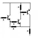
i made a prototype with 4 output transistors that works perfect ...so i made another one with 6 out per channel ..... the second prototype also works but when testing with 1 khz sinewave and 8 ohms resistive dummy load the lower part of wave form only gets distorted in some levels....somewhere in the midle when you feed the amp with 900mv or so
after that clears out and also before that looks almost clear ....
any opinions about that ????
An externally hosted image should be here but it was not working when we last tested it.
the outputs i use is mj 15003 -4 and here is the problem :
i made a prototype with 4 output transistors that works perfect ...so i made another one with 6 out per channel ..... the second prototype also works but when testing with 1 khz sinewave and 8 ohms resistive dummy load the lower part of wave form only gets distorted in some levels....somewhere in the midle when you feed the amp with 900mv or so
An externally hosted image should be here but it was not working when we last tested it.
after that clears out and also before that looks almost clear ....
any opinions about that ????
So, my question in the P3A thread has been answered ... seems that maybe the miller cap in the negative voltage driver is just for that ... what value do you have there ? You won't loose anything if you try and tweak it a little bit? ") (unless you make it too low and get oscillations)
(unless you make it too low and get oscillations)
My guess is that this is some kind of disadvantage of the bootstrap ... maybe, maybe not?
P.S. Just an off-topic question - if your output devices are TO-3, then what kind of drivers are you using ? (Q5,6,7,8)
(unless you make it too low and get oscillations)My guess is that this is some kind of disadvantage of the bootstrap ... maybe, maybe not?
P.S. Just an off-topic question - if your output devices are TO-3, then what kind of drivers are you using ? (Q5,6,7,8)
kalmara said:So, my question in the P3A thread has been answered ... seems that maybe the miller cap in the negative voltage driver is just for that ... what value do you have there ? You won't loose anything if you try and tweak it a little bit?
My guess is that this is some kind of disadvantage of the bootstrap ... maybe, maybe not?
P.S. Just an off-topic question - if your output devices are TO-3, then what kind of drivers are you using ? (Q5,6,7,8)
Probably with 6 pairs he need more miller capacitance. Try 500pf. Also some 10-100 ohm resistors in the drivers bases help too.
Also I'd lower R13 & 14 to 100 ohms or less. It adds stability at the expense of gain.
Now I'm always a fan of miller caps for the drivers. I use them for both upper and lower drivers with 100 ohm base resistors on an amp with 5 pairs. It is harder to get an amp stable with lots of parallel outputs, so you have to do extra stuff to get it to behave.
But for some reason some people here don't agree with me, but it works great. Miller caps for the drivers is a great thing IMO.
The lower half is oscillating. My bet is that it is because Q7 and Q8 are too slow - MJ15003/4 are 2MHz, and the MJL4281/4302 are 30MHz.
I would add 10 ohm resistors in the bases of all of the output transistors as recommended, but tbh I dont think this driver stage is going to work very well with slow transistors. You might be best simply using MJE15032/33 alone.
I would add 10 ohm resistors in the bases of all of the output transistors as recommended, but tbh I dont think this driver stage is going to work very well with slow transistors. You might be best simply using MJE15032/33 alone.
jaycee said:The lower half is oscillating. My bet is that it is because Q7 and Q8 are too slow - MJ15003/4 are 2MHz, and the MJL4281/4302 are 30MHz.
I would add 10 ohm resistors in the bases of all of the output transistors as recommended, but tbh I dont think this driver stage is going to work very well with slow transistors. You might be best simply using MJE15032/33 alone.
I've done it before with no problems. I've used 30mhz drivers on slower 2n3055/mj2955 Also, those MJE15032 are also 30mhz.
A miller cap on those 30mhz drivers will slow them down a bit.
The MJL's Ft is ~35MHz, while the MJ's are ~2MHz.
I'm almost sure your OP stage is oscillating.
First I'd reduce R13/R14 to ~33Ohm, an see what happens.
Anyway I'd replace the diode string with a Vbe multiplier for proper bias current adjustment.
What's you current bias?
Then MJE15033 is not a good choice for VAS purpose.
Same for Q1-Q2-Q3, tthese MPSA's are slow devices with low gain.
On the margin the whole amplifier needs a redsising IMHO.
I wondering why there are many fans of the ESP amplifiers...
The problem...
isn't slow vs fast outputs, or even slow vs. fast drivers. You can't just arbitrarily load down a CFP driver stage and just expect it to work. They don't scale up directly. They're finicky and layout-dependent. It can be made to work eventually, but while you all fool around with it inserting 100 different capacitors in as many locations, I'd just hook it up as a triple darlington with 1 or 2 ohm base stoppers on each output and have it working while everyone is still scratching their head.
isn't slow vs fast outputs, or even slow vs. fast drivers. You can't just arbitrarily load down a CFP driver stage and just expect it to work. They don't scale up directly. They're finicky and layout-dependent. It can be made to work eventually, but while you all fool around with it inserting 100 different capacitors in as many locations, I'd just hook it up as a triple darlington with 1 or 2 ohm base stoppers on each output and have it working while everyone is still scratching their head.
i would like to point
a few things ......
A)most esp designs i ve made or tested work like hell
B) the amplifier is working and its a tested design by rod but let us not forget that this is a test version that i ve made on my own pcb
C)the version i made with 4 transistors also works perfectly
D) rod has a version with aditional 4 transistors and no other changes at all .....so its either my pcb dont work properly or the choise of using the circuit as is together with mj15003-4 outs is wrong ....
i will try though a bigger miller cap plus base resistors to see what happens and let you know .....
thanks for the input
Re: The problem...
i dont exactly understand where these resistors are to be placed ......if you ll be kind enough to show me i would be very thankfull
thank you
wg_ski said:isn't slow vs fast outputs, or even slow vs. fast drivers. You can't just arbitrarily load down a CFP driver stage and just expect it to work. They don't scale up directly. They're finicky and layout-dependent. It can be made to work eventually, but while you all fool around with it inserting 100 different capacitors in as many locations, I'd just hook it up as a triple darlington with 1 or 2 ohm base stoppers on each output and have it working while everyone is still scratching their head.
i dont exactly understand where these resistors are to be placed ......if you ll be kind enough to show me i would be very thankfull
thank you
problem solved !!!!!!
10R 1/4w to every base of every out transistor and done with it ......looks ok
ac voltmeter gives almost 37 volts of out @ 1khz problem free at 4 or 8 ohms with 57.6 rails .......at 4ohms and full power i loose some 5-6 volts of my power supply .......
also ampere meter shows 4.6 amperes on the plus rail which if my calculations are correct gives more than 60% effecieny....guys help me here my maths are terrible
square wave though gets triancle after 4khz ......
there comes the vas miller cap game .....
lets see about that also
andy .....
andy .... you come to my help with very usefull sugestion many times .
really thank you for that .
sometimes though real experts like you or andrew t ( also been extremelly helpfull and for many times ) like to make perfect out of everything .......
you should try to see something like performance versus simplicity or like performance vercus cost and some other things related to that ........
i will give an example that i gave once before :
costumer of myshop was willing to pay almost 800 euros to buy from me a stereo P3 simply and nicelly made in a nice wooden box.....
i dint want to take money over rods design ( i actually offered him part of the money but he didnt take it since the pcb was designed by me ) but my costumer was ready to kill for this amp ....
the costumer was expirienced listener with about 3 pairs of good speakers (mission BW and kef) adcom preamps (2) arcam cd player lector amplifier and preamplifier and some other exotic stuff ....
he bought the P3 and the day after actually gave away his lector hybrid amp for a funny price of 800 euro since that this amp has a retail prize of 2.300 euros if i remember well ( perfect condition also )
does it make any sence ? well to me it does .....sonics ......
Andy L. Francis said:The MJL's Ft is ~35MHz, while the MJ's are ~2MHz.
I'm almost sure your OP stage is oscillating.
First I'd reduce R13/R14 to ~33Ohm, an see what happens.
Anyway I'd replace the diode string with a Vbe multiplier for proper bias current adjustment.
What's you current bias?
Then MJE15033 is not a good choice for VAS purpose.
Same for Q1-Q2-Q3, tthese MPSA's are slow devices with low gain.
On the margin the whole amplifier needs a redsising IMHO.
I wondering why there are many fans of the ESP amplifiers...
andy .... you come to my help with very usefull sugestion many times .
really thank you for that .
sometimes though real experts like you or andrew t ( also been extremelly helpfull and for many times ) like to make perfect out of everything .......
you should try to see something like performance versus simplicity or like performance vercus cost and some other things related to that ........
i will give an example that i gave once before :
costumer of myshop was willing to pay almost 800 euros to buy from me a stereo P3 simply and nicelly made in a nice wooden box.....
i dint want to take money over rods design ( i actually offered him part of the money but he didnt take it since the pcb was designed by me ) but my costumer was ready to kill for this amp ....
the costumer was expirienced listener with about 3 pairs of good speakers (mission BW and kef) adcom preamps (2) arcam cd player lector amplifier and preamplifier and some other exotic stuff ....
he bought the P3 and the day after actually gave away his lector hybrid amp for a funny price of 800 euro since that this amp has a retail prize of 2.300 euros if i remember well ( perfect condition also )
does it make any sence ? well to me it does .....sonics ......
Re: problem solved !!!!!!
10 ohms resistors as Base stoppers is what professor Leach uses/recommends for output in his both power amplifiers.
I think an optimal resistance value is related to specific devices used and how fast transistors are.
My guess is we could try resistors in range of: 2.2 - 15 Ohms.
And that the precise value is not always very critical.
More important is to put these resistors as close as practically possible to Transistor Base.
This is even more important for MOSFET Gate resistors..
W. Marshall Leach, Jr., Professor - Audio Related Things
His collection of articles and papers
lineup amplifier regards
sakis said:10R 1/4w to every base of every out transistor and done with it ......looks ok
10 ohms resistors as Base stoppers is what professor Leach uses/recommends for output in his both power amplifiers.
I think an optimal resistance value is related to specific devices used and how fast transistors are.
My guess is we could try resistors in range of: 2.2 - 15 Ohms.
And that the precise value is not always very critical.
More important is to put these resistors as close as practically possible to Transistor Base.
This is even more important for MOSFET Gate resistors..
W. Marshall Leach, Jr., Professor - Audio Related Things
His collection of articles and papers
lineup
amplifier regardsAndy L. Francis said:The MJL's Ft is ~35MHz, while the MJ's are ~2MHz.
I'm almost sure your OP stage is oscillating.
First I'd reduce R13/R14 to ~33Ohm, an see what happens.
Anyway I'd replace the diode string with a Vbe multiplier for proper bias current adjustment.
What's you current bias?
Then MJE15033 is not a good choice for VAS purpose.
Same for Q1-Q2-Q3, tthese MPSA's are slow devices with low gain.
On the margin the whole amplifier needs a redsising IMHO.
I wondering why there are many fans of the ESP amplifiers...
I have built numerous amps with the MPSA42 and they all work very well.
With 6 MOSFETS I use a 220pf miller cap and 12ma VAS current.
I found less than 220pf caused oscillation.
Thats quite a simple amp cct, I prefer something simple, its easier to fix if something goes wrong.
Others like to add lots of complicated extras but being from a commercial background minimal is good from the expense point of view.
Re: i would like to point

Sorry, not true. He adds another Zobel.
MJ15003-04 are not part of his recommendations. If you see the picture of his PCB, using TO-264 case parts keeps the leads of the transistors VERY short. Using TO-3 parts could force long lead wires which could affect this SUBWOOFER recommended design (not full frequency range).
We all must be careful when changing a designer's design/PCB.

sakis said:D) rod has a version with aditional 4 transistors and no other changes at all .....
Sorry, not true. He adds another Zobel.
MJ15003-04 are not part of his recommendations. If you see the picture of his PCB, using TO-264 case parts keeps the leads of the transistors VERY short. Using TO-3 parts could force long lead wires which could affect this SUBWOOFER recommended design (not full frequency range).
We all must be careful when changing a designer's design/PCB.
Saki
From the scope picture it is obvious that you have also a little distortion in the positive swing part.
As you wrote, you added one pair more of output transistors. If you use the same supply level, i suspect that you have a voltage drop from the original voltage level. This means that (because you are using a fixed Vbe multiplier) the Iq has dropped also. If it is so, try to increase it by changing the values of R10-R11 by experimenting so to obtain the original Iq.
Check it, i express only thoughts... please.
If i was in your place i'll made also the following experiments:
1) Remove the R6 and join the collector of Q3 directly to +V. Remove also the emiter of Q4 from +V rail and place between them a resistor of 47R.
Make a test again
2) Try to desolder C6 and make again a measurement.
3) Play a little with the value of R7 from 560R down to 180R with different values.
Take oscillographs during this.
You don't refffer if you have made measurements without load and which is the result.
Please make these experiments and give your results.
Fotios
- Status
- This old topic is closed. If you want to reopen this topic, contact a moderator using the "Report Post" button.
- Home
- Amplifiers
- Solid State
- p68 trouble .....