john curl said:I have always been plagued with a residual 7th harmonic ..
/snip/
Maybe there is a solution.
Increased 2'nd or 3'rd isn't very important in my case.
Something like this maybe.
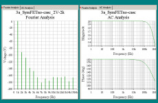
My simulation work of the day.
Based on commonly avialable: 2 N-JFET + 2 P-JFET
in a stragth forward complementary symmetrical DCin -> DCout configuration.
One 'complementary' pair for input and the other pair for push-pull output stage.
Supported by current mirrors acorrding to John Curl ( emitter resistors! ).
Supply is +18 VDC and -18 VDC
The gain is +20dB ( x10 )
Output is 2 Vrms into 2 kOhm load.
I did only have to us one little capacitor for this circuit!
10 pF, as in AD797, to tame the output overloading.
Result is close to perfect phase behavior and a roll-off nicely at 500 kHz
The graphs of multi-sim testing is in my attachment.
lineup
") hifi regards, without much of the 7th degree torture
hifi regards, without much of the 7th degree tortureAttachments
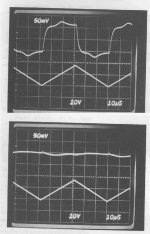
Here's the pix from my AES paper showing the operation of Cn (AD797). The tri-wave represents +-10mA of current being shoved into the output. The other plot is the input error signal (I forgot the exact scale). I like tri-wave excitation because main error signal is then a square wave (derivative) and the crossover jumps right out. The lower picture shows amount of removal of both errors.
Attachments
john curl said:Little points of distortion concern me.
That's the tri-wave changing slope the derivative is discontinuous, no test is perfect. If you play with class A current injection you can move the crossover "hat" around and deduce the bias level and see if positive or negative current looks better.
anyone willing to email the aes paper? - my local uni library discontinued aes preprints the year before:
An Operational Amplifier Architecture with a Single Gain Stage and Distortion Cancellation
Amplifiers with a single high gain stage are attractive for their simplicity and excellent power/performance tradeoff, but their typically higher distortion has limited their use in the audio field. Presented here will be a low power single-stage amplifier architecture that enables passive cancellation of distortion (THD < -120 dB, @ 20 kHz). Classical output stage distortion as well as nonlinear capacitive effects will be addressed.
Paper Number: 3231 Convention: 92 (March 1992)
Author: Wurcer, Scott
Affiliation: Analog Devices Semiconductor, Wilmington, MA
jcx said:anyone willing to email the aes paper? - my local uni library discontinued aes preprints the year before:
An Operational Amplifier Architecture with a Single Gain Stage and Distortion Cancellation
Amplifiers with a single high gain stage are attractive for their simplicity and excellent power/performance tradeoff, but their typically higher distortion has limited their use in the audio field. Presented here will be a low power single-stage amplifier architecture that enables passive cancellation of distortion (THD < -120 dB, @ 20 kHz). Classical output stage distortion as well as nonlinear capacitive effects will be addressed.
Paper Number: 3231 Convention: 92 (March 1992)
Author: Wurcer, Scott
Affiliation: Analog Devices Semiconductor, Wilmington, MA
If you have no takers I could scan it in or send you a copy by regular mail, I think I have more than one left.
Edit - I could Xerox it too, what a concept.
jcx said:anyone willing to email the aes paper?
I have it in pdf, so if anyone need it, please mail me.
More (simulated) fun with AD797 compensation
I updated my simplified AD797 sim circuit with a few values from the AES paper – still a long ways from the full circuit and qualified process models that Scott must have
I am trying to illustrate 2 different compensation schemes:
i. the data sheet mixed decomp/”distortion cancellation” C divider
ii. 2-pole T network using the Cn local feedback/decompensation port
with 2 different measurements:
i. loop gain measured inside both feedback loops – which I believe shows that “distortion cancellation” is loop gain and which better measures the stability of the circuit – and illustrates that I have nearly the same loop gain for both example compensations, ie apples to apples comparison
ii. loop gain measured inside the resistive gain setting feedback loop but outside of the Cn local feedback – which in this case captures the loop gain available to reduce op amp input stage distortion as well as reduce output stage impedance and distortion
both plots include both compensations in duplicated circuit blocks, only one circuit shown for each
I used 30 dB for the gain to be as relevant as such a simplified sim can be to Mr Curl's investigations
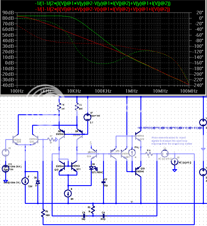
Inner most loop gain: (green = T comp, red = Analog's comp circuit shown)
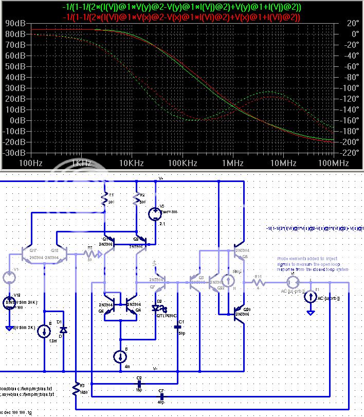
Outer loop gaingreen = T comp circuit shown, red = Analog's)
I believe the above sims illustrate T compensation could provide better distortion reduction over the audio frequency range compared to Analog's suggested compensation/distortion cancellation circuit
another advantage of the T compensation shown is the boosting the negative rail psrr, the improvement is very nearly the difference seen in the outer loop measurement of loop gain
I updated my simplified AD797 sim circuit with a few values from the AES paper – still a long ways from the full circuit and qualified process models that Scott must have
I am trying to illustrate 2 different compensation schemes:
i. the data sheet mixed decomp/”distortion cancellation” C divider
ii. 2-pole T network using the Cn local feedback/decompensation port
with 2 different measurements:
i. loop gain measured inside both feedback loops – which I believe shows that “distortion cancellation” is loop gain and which better measures the stability of the circuit – and illustrates that I have nearly the same loop gain for both example compensations, ie apples to apples comparison
ii. loop gain measured inside the resistive gain setting feedback loop but outside of the Cn local feedback – which in this case captures the loop gain available to reduce op amp input stage distortion as well as reduce output stage impedance and distortion
both plots include both compensations in duplicated circuit blocks, only one circuit shown for each
I used 30 dB for the gain to be as relevant as such a simplified sim can be to Mr Curl's investigations
Inner most loop gain: (green = T comp, red = Analog's comp circuit shown)
Outer loop gain
green = T comp circuit shown, red = Analog's)An externally hosted image should be here but it was not working when we last tested it.
I believe the above sims illustrate T compensation could provide better distortion reduction over the audio frequency range compared to Analog's suggested compensation/distortion cancellation circuit
another advantage of the T compensation shown is the boosting the negative rail psrr, the improvement is very nearly the difference seen in the outer loop measurement of loop gain
Attachments
phase margin is most important near the 0 dB loop gain intercept where output stage loading can reduce gain by small amounts - generic control loop practice considers 12 dB gain margin adequate, and while 60 degree phase margin at the 0 dB intercept is pretty "industry standard" some high performance loops are designed with 30-45 degree margins - input/command low pass pre-filters recommended
for the ~20 degree phase margin near 100 KHz to have any stability consequence the loop gain must be reduced by ~30-40 dB, Gerald Graeme refers to this as "gain stabilization"
and the lower picture's T compensation plot showing the small phase margin @ 100 KHz is a plot of the outer loop gain only
I believe the stability with respect to output stage loading gain reduction is governed by the gain plotted in the picture above that: loop gain measured inside both feedback loops enclosing the output stage - for which there is little difference in the 2 compensation scheme's gain/phase
the lower plot of the T compensation does suggest slew rate limiting in the input stage could cause "describing function sense" gain reduction that could make the low phase margin noticeable
but the AD797's hot diff pair bias gives 1.8 mA / 50 pF = 36 V/uS slew rate limit - which shows the output stage will clip at the supply rails at 100 KHz before slew rate limiting even begins - much less reaches 30-40 dB of describing function gain reduction required to make the plotted low outer loop 100 KHz phase margin problematic
the proof of the concept will be in playing with a hardware implementation – I really doubt that at the discussed audio signal levels that there is any easily measurable way to distinguish them – the base AD797 performance is just so high to start with
a couple of quick sims suggests the T compensation is more robust to C loads up to 3 nF, 10 Ohms series R keeps both simmed compensations well behaved even with 10 nF C load
I see a possible confusion - the loop gain plotted above is the "excess loop gain" with the 30 dB feedback gain setting accounted for automatically
0 dB on these plots is the "gain intercept" where the op amp open loop gain is +30 dB and matches the feedback network's -30 dB attenuation (actually the inner loop plot includes the effect of Cn local feedback which may "tilt" the loop gain and give a slighly higher gain intercept frequency)
if you look at the lower plot's -30 dB intercept, which would be ~ the op amp open loop unity gain point you can read off ~ 10 degree phase margin - evidence of the decompensation in action
the Cload test comment I tacked on above was performed with .tran, 1 nS time steps, the datasheet recommended compensation was fully oscillating with 5 nF C load while the T compensated sim's ringing damped out
by playing with higher gains (> Av 10) and decompensation I hope many high frequency (>10 MHz) modeling differences can be safely ignored
I'm unconvinced that settling time of MHz bandwidth feedback amplifiers is really relevant to audio reproduction - certainly 2-pole compensations can cause long settling tails but most audio signals will have been 2nd order low pass filterd by microphones and electronics at <100 KHz, usually <20-30 KHz when speaker dynamics are added in
but for high speed instumentaion applications I could believe the "single-pole" output loop response is attractive
Do you have any comment with respect to the Ccomp production spread and how much active device junction C contributes to Voltage sensitivity of the compensation tuning? - I find trimming Cn to 1% "profitable" in sim - but in the real world?
jcx said:by playing with higher gains (> Av 10) and decompensation I hope many high frequency (>10 MHz) modeling differences can be safely ignored
I'm unconvinced that settling time of MHz bandwidth feedback amplifiers is really relevant to audio reproduction - certainly 2-pole compensations can cause long settling tails but most audio signals will have been 2nd order low pass filterd by microphones and electronics at <100 KHz, usually <20-30 KHz when speaker dynamics are added in
but for high speed instumentaion applications I could believe the "single-pole" output loop response is attractive
Do you have any comment with respect to the Ccomp production spread and how much active device junction C contributes to Voltage sensitivity of the compensation tuning? - I find trimming Cn to 1% "profitable" in sim - but in the real world?
There is probably some sensitivity definately more than 1%. I still would like to make a fully complimentary version.
Yeah, of course. I am honored you askECBLN said:@ lineup
Hi, can you send me your multisim file ?
thx
Send me an Email and you get it. Click My Email button below this post.
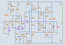
By the way, I can send you my simulation of Grundig amplifier, too.
It is a Very Good amplifier! Good MultiSim test-results.
Lots of work done to compensate (many small pF caps).
See attachment, please. / Lineup
Attachments
I still would like to make a fully complimentary version.
Have you done so, Scott? If not, can you try to make it now?
THx-RNMarsh
- Status
- This old topic is closed. If you want to reopen this topic, contact a moderator using the "Report Post" button.
- Home
- Amplifiers
- Solid State
- Class A biasing for the AD797?