making Upgrade III
I have try modification on other amp
about capacitor on NFB and results are unbelivable
also because the zero point on output is 0.3 - 0.4 VDC
so that little circuit is only a compressor!
now want modify mirror stage with discrete like Rotel RA971MKII
and thinking about bridge to have a true Hi-End AMP...
Attachments
Very Good Have Complementary Input
in my last research about amplifier
can say 2 important quality:
1 - have complementary input
like your schematic with OP-AMP
2 - cancel capacitor (shorth) in NFB ring
because is a terrible filter!
but OP-AMP have inside this kind of circuit...
so on e-bay found a ROTEL series 9 or better 10
like mine RB970
the image that is created behind the speakers
has significantly improved in detail and depth
besides having a sober timbre as the subwoofer amplifier
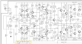
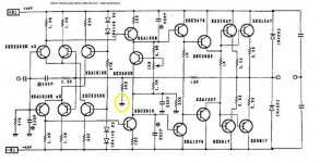
simple shorth cap on -input
see schematic
on NFB (inverting input) there is not capacitor
but you need two on output
because there is not DC offest now
(really very little about 0.3V)
you can find original one
RB-971 BX
http://fileshare.eshop.bg/downloadsm/22508/Rotel_RA-971 MkII.html
see schematic
on NFB (inverting input) there is not capacitor
but you need two on output
because there is not DC offest now
(really very little about 0.3V)
you can find original one
RB-971 BX
http://fileshare.eshop.bg/downloadsm/22508/Rotel_RA-971 MkII.html
Attachments
about the schematic i've posted previously....
i've build this amp for testing only, and it's working, from some time....indeed it's pretty detailed (at least to my ears). but in my case load (speaker) is "grounded", i mean the center tap from the transformer.
do you think that if load is connected with 2 capacitors to the supplies as you said (instead of ground, like now) will help to the overall quality of sound (soundstage/detail/focus etc) ?
thanks, Tibi
anyway i agree that the nfb-capacitor have some influence on amplifier response (sound), but i think this is also true if we short this one and connect the load with other 2 capacitors to the rails....now influence will be set by these 2, much bigger than nfb one. so i guess you must have 2 very good capacitors to the rails. and also the price may jump a little bit in this case.
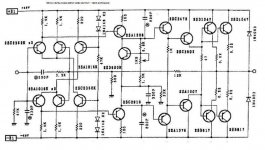
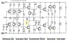
balanced capacitors test
Is simple test this configuration
do you have two capacitors?
for sure don't make imprinting on sound
because are in balanced mode
this function is different from traditional DC OFFSET in negative input
i'm making a PCB for this circuit with new transistor
from MOTOROLA and TOSHIBA...
Is simple test this configuration
do you have two capacitors?
for sure don't make imprinting on sound
because are in balanced mode
this function is different from traditional DC OFFSET in negative input
i'm making a PCB for this circuit with new transistor
from MOTOROLA and TOSHIBA...
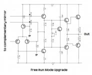
one is serial mode - two are paralleled
Stee: That's neat - half-bridge, in other words. You need two caps instead of one, but the ripple current requirement of each cap gets halved, because there are now two charge/discharge paths.
Free Run Mode: charge/discharge don't have load between.
See important Upgrade at this project:
local feedback (without capacitor)
one stage in current near final
Attachments
Very interesting amp design!!! 
It doesn't follow the "rules" of most amps, I like that!
I've been wanting to make a 4 channel amp for 60Wx4 @ 4 ohms but making 4 descrete amps on one PCB takes a lot of space, so your op-amp idea seems ideal. One quad op-amp is much smaller than 4 descrete LTP stages, and easy to fix if the chip is in a socket.
Only concern is if the op-amp solution sounds as good as descrete for Hi-Fi use. If I do this, I'd like to use the On-Semi MC33079 quad opamp because of the 0.002%THD
Also, is the op-amp drive ok for heavy sub use, or is descrete still better? If necessary, I imagine you could parallel 4 op-amps in a quad chip for the required drive current.
Only difference IMO I'd make is to use a lower voltage dedicated +/- power supply for the opamp instead of zeners.
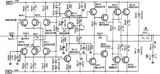
my last research
http://fileshare.eshop.bg/downloadsm/22851/Rotel_RMB-1048.html
if you can find on ebay RB-976 MKII
IS STRONGLY RACCOMANDED
for six ch - 3 ch in bridge (balanced) - small space
cut and shorth capacitors:
the DC OFFSET is 0.1V!
put bias from 5mV to 20mV
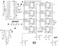
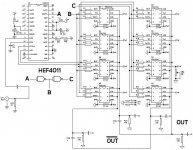
for this SuperAMP i have modified TDA DAC
with NAND gate (HEF4011B) on DATA
to have balanced output (4+4 TDA)
...superior sound
please don't use OP-AMP

http://fileshare.eshop.bg/downloadsm/22851/Rotel_RMB-1048.html
if you can find on ebay RB-976 MKII
IS STRONGLY RACCOMANDED
for six ch - 3 ch in bridge (balanced) - small space
cut and shorth capacitors:
the DC OFFSET is 0.1V!
put bias from 5mV to 20mV
for this SuperAMP i have modified TDA DAC
with NAND gate (HEF4011B) on DATA
to have balanced output (4+4 TDA)
...superior sound
please don't use OP-AMP
Attachments
"this solution expand your sound like a tube amp"
So, that's what's needed to get SS stuff to sound like tubes - two ugly electolytics at output. And to think amp designers have been trying to get rid of those for years. What morons.
Tube sound = capacitor distortion + free dc protection
So, that's what's needed to get SS stuff to sound like tubes - two ugly electolytics at output. And to think amp designers have been trying to get rid of those for years. What morons.
Tube sound = capacitor distortion + free dc protection
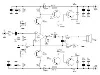
fully balanced for tube sound
really the capacitors are only for protect speakers
for safety
BUT
if you have two AMPs in bridge
DO NOT NEED
DC offset in Free Run (without integrator on inverted input)
the gap is only 0.15V
but you need balanced DAC
to drive correctly twin amp for channel
and 4 potentiometer works togheter for volume
better way is have 4 amp with complementary mirror
and balanced loudspeakers like mine
www.esafono.it
Re: fully balanced for tube sound
and certainly can be done with dual pot for 2channel volume adjustment.
simply a balanced feed to the amps, not necessarily a balanced DAC.Stee said:.....you need balanced DAC
to drive correctly twin amp for channel
and 4 potentiometer works together for volume
and certainly can be done with dual pot for 2channel volume adjustment.
Balanced signal
chip LB1639 SANYO
make this job - balance the unbalanced signal
difficult to found - use DENON PMA1500
viceversa balanced DACs have 2 quality:
1 - delete the same carrier without filter (44.1 KHz) because make difference the AMPs
2 - delete emphasys of single DAC because works exactly at
the same time in opposite phase - is like PNP NPN compensation
for that reason i have tryed to put RF filter between hot and cold
Attachments
- Status
- This old topic is closed. If you want to reopen this topic, contact a moderator using the "Report Post" button.
- Home
- Amplifiers
- Solid State
- Simply the Best - LiveWave AMP