re - balanced capacitors test
Hi, Stee
I did the test, regarding my amplifier (posted before). I put 2 capacitors 4700uF between the speaker (-) and the supply rails, on every channel (speaker (-) disconnected from GND, as in your schematics).
But after this sound wasn't as clear as before and a little bit of "air" from soudstage has dissapeared. Also there was present little hum (100hz), which I didn't heard until then.
Maybe is about this particular case, because in my amplifier there is already no nfb capacitor and putting capacitors makes signal path less "clean" than direct grounding.
Regards, Tibi
Re: SEE THE TEAM
You will not get the amp stable with those transistors. Also, the gain of the MPSA devices aren't enough. Try 2N5401/5551 or the 2SA970 and 2SC2240 for the input pair. Lastly, you might need to add emitter degeneration for the input pair so the dc operating point can stabilise at those voltages. This will impact distortion performance though. It is still best to stick to the specified transistors.
For the VAS you should use other transistors, like the 2SA1142 and 2SC2682.
You will still battle to stabilise it though, having to resort to Miller compensation on the VAS. Trust me, I've cloned that circuit too and this is what I've had to do...
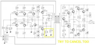
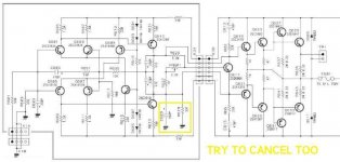
Stee said:in this drawing ca see the components of Free Run Mode AMP
may be compare with BD139/140 TIP31C/32C 2SA1215/C2922
do you have alternative for MPSA?

You will not get the amp stable with those transistors. Also, the gain of the MPSA devices aren't enough. Try 2N5401/5551 or the 2SA970 and 2SC2240 for the input pair. Lastly, you might need to add emitter degeneration for the input pair so the dc operating point can stabilise at those voltages. This will impact distortion performance though. It is still best to stick to the specified transistors.
For the VAS you should use other transistors, like the 2SA1142 and 2SC2682.
You will still battle to stabilise it though, having to resort to Miller compensation on the VAS. Trust me, I've cloned that circuit too and this is what I've had to do...
I'm sorry, although it might be a very good circuit and so on, I feel like I saw it too much in my electronics books when I was young(many years ago heh) and even then i thought "noo , I'm not building that.."
hmm I remember a few amplifiers in the Oppermann catalog that I wanted to build then, hmm maybe I still have the old catalog somewhere. I think Im going to search a bit for it and look what I think of them now ;-) :-D hehe.. could be interresting..
hmm I remember a few amplifiers in the Oppermann catalog that I wanted to build then, hmm maybe I still have the old catalog somewhere. I think Im going to search a bit for it and look what I think of them now ;-) :-D hehe.. could be interresting..
Re: re - balanced capacitors test
strange
may be need a load to ground like 47R (to + out and ground)
for the air dissappared
may be need more capacity
or less power...
do you have short also NFB cap?
fojica said:Hi, Stee
I did the test, regarding my amplifier (posted before). I put 2 capacitors 4700uF between the speaker (-) and the supply rails, on every channel (speaker (-) disconnected from GND, as in your schematics).
But after this sound wasn't as clear as before and a little bit of "air" from soudstage has dissapeared. Also there was present little hum (100hz), which I didn't heard until then.
Maybe is about this particular case, because in my amplifier there is already no nfb capacitor and putting capacitors makes signal path less "clean" than direct grounding.
Regards, Tibi
strange
may be need a load to ground like 47R (to + out and ground)
for the air dissappared
may be need more capacity
or less power...
do you have short also NFB cap?
Re: Re: SEE THE TEAM
thanks a lot for your help gbyleveldt
now i'm searching to buy japan family

gbyleveldt said:
You will not get the amp stable with those transistors. Also, the gain of the MPSA devices aren't enough. Try 2N5401/5551 or the 2SA970 and 2SC2240 for the input pair. Lastly, you might need to add emitter degeneration for the input pair so the dc operating point can stabilise at those voltages. This will impact distortion performance though. It is still best to stick to the specified transistors.
For the VAS you should use other transistors, like the 2SA1142 and 2SC2682.
You will still battle to stabilise it though, having to resort to Miller compensation on the VAS. Trust me, I've cloned that circuit too and this is what I've had to do...
thanks a lot for your help gbyleveldt
now i'm searching to buy japan family
try the new idea it's easy
really don't need capacitors on final stage
because if you have a good commercial amplifier (bipolar made)
you can measure the DC offset on a resistor load
when have shorted NFB capacitor...
is around 0.3V
stable
with medium speakers is safety too
and you can feel this new air near your room
for me it's a good news,
like connect a tube amplifier
without transformer (OTL)
nikwal said:I'm sorry, although it might be a very good circuit and so on, I feel like I saw it too much in my electronics books when I was young(many years ago heh) and even then i thought "noo , I'm not building that.."
hmm I remember a few amplifiers in the Oppermann catalog that I wanted to build then, hmm maybe I still have the old catalog somewhere. I think Im going to search a bit for it and look what I think of them now ;-) :-D hehe.. could be interresting..
really don't need capacitors on final stage
because if you have a good commercial amplifier (bipolar made)
you can measure the DC offset on a resistor load
when have shorted NFB capacitor...
is around 0.3V
stable
with medium speakers is safety too
and you can feel this new air near your room
for me it's a good news,
like connect a tube amplifier
without transformer (OTL)
Re: try the new idea it's easy
The transformer in a tube amp does more than just DC blocking. It is there to match the high impeadance of the tube output stage to the low inpeadance of the speaker. I'm sure tube amp designers would love to not have to use output iron.
....like connect a tube amplifier
without transformer (OTL)
The transformer in a tube amp does more than just DC blocking. It is there to match the high impeadance of the tube output stage to the low inpeadance of the speaker. I'm sure tube amp designers would love to not have to use output iron.
YESwhoandcar said:There was a time... many years ago, when Philips designed 600 ohm speaker to couple directly to single ended tube power stages (low power, such as TV and record players) and to get rid of the O/P transformer.
my friend have buy two on ebay
also have founded two speakers 800 ohm
I heard them many times
very very good
because...
have capacitors on output!
it's true, I saw them inside.
Re: Re: try the new idea it's easy
Indeed, my thesis is that the tube sounds better
because it does not need adjustment automatic DC offset
valves play free with transformer
see the best buy 2008 (8ch)
ROTEL RMB 1048 modified
then connected in parallel and bridge (2 compl AMP for each rail)
CBS240 said:
The transformer in a tube amp does more than just DC blocking. It is there to match the high impeadance of the tube output stage to the low inpeadance of the speaker. I'm sure tube amp designers would love to not have to use output iron.
Indeed, my thesis is that the tube sounds better
because it does not need adjustment automatic DC offset
valves play free with transformer
see the best buy 2008 (8ch)
ROTEL RMB 1048 modified
then connected in parallel and bridge (2 compl AMP for each rail)
Attachments
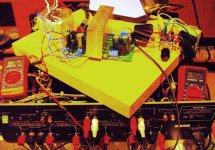
Forget Capacitors on Output
I'm testing RB-976 from 10 days in bridge
without famous NFB capacitors
see picture (see also TDA balDAC)
one channel have 76mV other -40mV of DC gap
maximum have found double time (150mV)

don't understand function of this orrible old design
may be in the past amplifier was very unbalanced?
try with your amp with a power resistor for load
... may be have no more then 350mV

I'm testing RB-976 from 10 days in bridge
without famous NFB capacitors
see picture (see also TDA balDAC)
one channel have 76mV other -40mV of DC gap
maximum have found double time (150mV)
don't understand function of this orrible old design
may be in the past amplifier was very unbalanced?
try with your amp with a power resistor for load
... may be have no more then 350mV
Attachments
Re: Re: re - balanced capacitors test
hi, Stee
some details...as i already said, in my schematic/amplifier is no nfb capacitor (see attachment on post 25).
i found this schematic on a russian site and i gave it a try because seems interesting at that time (and it is still the case, so far).
on the output, grounded (normal) mode, i have 2mV on R channel and 3.7mV on L, DC offset. i didn't try to adjust the offset on TL071s, these are "default" levels.
i will redo the test in the following days, putting 4x4700uF/channel and with 47R between out(+) and GND, as you suggested.
regards,
Tibi
Stee said:
strange
may be need a load to ground like 47R (to + out and ground)
for the air dissappared
may be need more capacity
or less power...
do you have short also NFB cap?
hi, Stee
some details...as i already said, in my schematic/amplifier is no nfb capacitor (see attachment on post 25).
i found this schematic on a russian site and i gave it a try because seems interesting at that time (and it is still the case, so far).
on the output, grounded (normal) mode, i have 2mV on R channel and 3.7mV on L, DC offset. i didn't try to adjust the offset on TL071s, these are "default" levels.
i will redo the test in the following days, putting 4x4700uF/channel and with 47R between out(+) and GND, as you suggested.
regards,
Tibi
Re: Re: Re: try the new idea it's easy
Stee, regarding the image you attached in the above post. Those caps are there in a shunt across the VAS for compensation. They are critical to stabilise the amp for those specific transistors. Using other transistors would force you to use other compensation mechanisms. Either way, you will have to compensate somehow, no matter what transistors you end up using. Think twice before removing any caps from an amplifier, you might just end up with burnt silicon and/or fired speakers.

Stee said:
Indeed, my thesis is that the tube sounds better
because it does not need adjustment automatic DC offset
valves play free with transformer
see the best buy 2008 (8ch)
ROTEL RMB 1048 modified
then connected in parallel and bridge (2 compl AMP for each rail)
Stee, regarding the image you attached in the above post. Those caps are there in a shunt across the VAS for compensation. They are critical to stabilise the amp for those specific transistors. Using other transistors would force you to use other compensation mechanisms. Either way, you will have to compensate somehow, no matter what transistors you end up using. Think twice before removing any caps from an amplifier, you might just end up with burnt silicon and/or fired speakers.
Searching definitive solution
I have a diagram on paper
T-90 AM Audio built not far from my house
when I have the scanner working ...
and also that resistor and capacitor are gone
compared to the classic pattern
I believe that another default by engineers !
of course I am prepared to risk a transistor
but not the speakers
use the output resistor/then capacitors to measure/prove
for sure
where you can better simplify
Attachments
Re: again about op-amp driver
hi, Stee
i guess maybe it's a bit tricky...but....this is not a traditional class AB amplifier, it's current dumping principle. that means existence of an alternative current bridge...and R10 is part of that bridge, composed by R10-C3-R11-L1. accuracy of the bridge has pretty big importance on amplifier response, so R10 can't go...this is my point of view after reading some documentation about Quad405 and current dumping principles.
please correct me if i'm wrong.
also the op-amp don't drive speaker directly (DC-mode), because there is C2 and JP1(jumper)...C2 is not really needed because original schematic had 741 as op-amp,and the 741 needed some correction...but for TL071 it's not the case. so, JP1 can be in "open" state and then is no direct connection between op-amp and speaker. in fact, JP1 is currently open in my case (his short/open state influence i found being null so far). if it useful somehow i can give the original link, where can be found original schematic and also some details about that one posted by me.
regards,
Tibi
Stee said:in your case R10 don't need
op-amp don't have to drive speaker
hi, Stee
i guess maybe it's a bit tricky...but....this is not a traditional class AB amplifier, it's current dumping principle. that means existence of an alternative current bridge...and R10 is part of that bridge, composed by R10-C3-R11-L1. accuracy of the bridge has pretty big importance on amplifier response, so R10 can't go...this is my point of view after reading some documentation about Quad405 and current dumping principles.
please correct me if i'm wrong.
also the op-amp don't drive speaker directly (DC-mode), because there is C2 and JP1(jumper)...C2 is not really needed because original schematic had 741 as op-amp,and the 741 needed some correction...but for TL071 it's not the case. so, JP1 can be in "open" state and then is no direct connection between op-amp and speaker. in fact, JP1 is currently open in my case (his short/open state influence i found being null so far). if it useful somehow i can give the original link, where can be found original schematic and also some details about that one posted by me.
regards,
Tibi
where you can better simplify
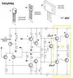
this is the direction of my project ( now renamed EASYMAG )
again from T-90 schematic...
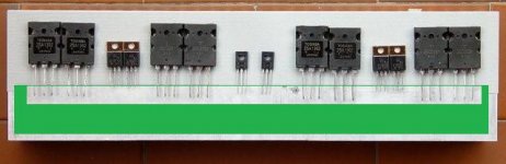
1 - Use only 3 size of transistors (Little Medium and Big)
2 - VAS is most critical, so better put a current stage
3 - Final stage is better double also for driver (in parallel)
now see this architecture
is becoming very interesting
... who wants to book a printed circuit board?
coming soon
this is the direction of my project ( now renamed EASYMAG )
again from T-90 schematic...
1 - Use only 3 size of transistors (Little Medium and Big)
2 - VAS is most critical, so better put a current stage
3 - Final stage is better double also for driver (in parallel)
now see this architecture
is becoming very interesting
... who wants to book a printed circuit board?
coming soon
Attachments
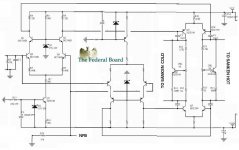
larger image of Easymag2
http://www.esafono.it/easymag2.jpg
from LiveWave to ----> EasyMag2
stay on-line
http://www.esafono.it/easymag2.jpg
from LiveWave to ----> EasyMag2
stay on-line
Attachments
- Status
- This old topic is closed. If you want to reopen this topic, contact a moderator using the "Report Post" button.
- Home
- Amplifiers
- Solid State
- Simply the Best - LiveWave AMP