hi all,
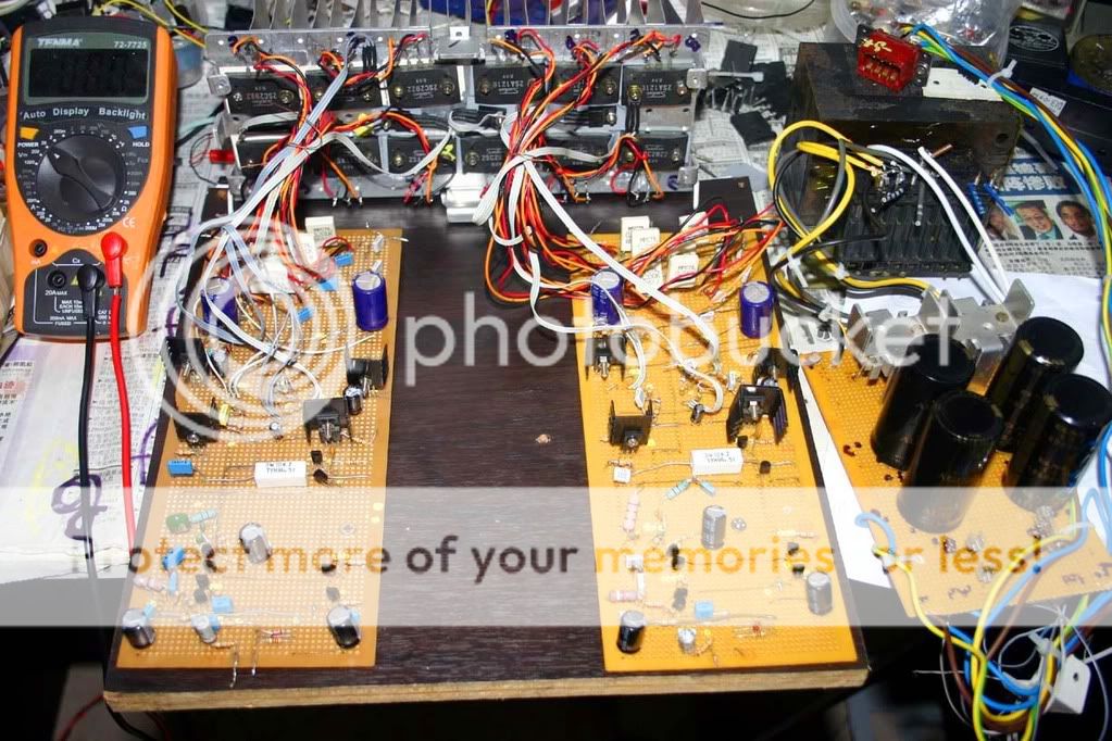
i have just made one amp from DX-Precision-I, first i have to say i am not good in electronics, sorry, i am a good listener. this is my own made but the power amp circuit design from DX. lcd is my own project, not taken from any where. i wrote my own software for relay and some switch to control. i used pic16f877.
original transistors "snkn". it dsn't get much hot as i used low mlv at output. very stable with good sound. i am going to try hrii too. i will make srval amp to compare and keep for my own.
you can see it is not so nice looks but it works great. even i know the way i made is not right. if i can buy pcb for it, i know the sound will be much more btr then now.
thank to all.
michael
http://i275.photobucket.com/albums/jj292/space2000/IMG_0295-2.jpg
Re: man......
Why? The electrons don't mind.
I would even use breadboard.
sakis said:this the most ugly thing i ve ever seen in my life
Why? The electrons don't mind.
I would even use breadboard.
hi,
i don't know how you feels for the construction. it's sound is really great, honestly tells you. i love this amp sound. i will re construct it but not now until i can make a pcb board. now i am trying how can i make my own pcb board by using dx pcb design.
i am looking for any easy way to make pcb at home. also needs to get hsink to seperate them into two. it is running 40+ c and coold in low vol.
thank you.
Re: man......
I build all my amp driver stages on Veroboard too and never had any problems, they have sounded great.
The trick with veroboard and all those wires hanging everywhere is to keep things neat so they cant short out.
Once everything is wired up I cable tie or lace the power cables together to stop things moving around and wires breaking off.
The same goes for the small signal and powerlines.
I would never lace in small signal and power signals in the same loom as you can sometimes get cross talk and unwanted feedback.
Looks like a good effort to me for a beginner.
Proper PCB's would be nicer but can be expensive, thats why i use veroboard with components well spaced out.
sakis said:this the most ugly thing i ve ever seen in my life
I build all my amp driver stages on Veroboard too and never had any problems, they have sounded great.
The trick with veroboard and all those wires hanging everywhere is to keep things neat so they cant short out.
Once everything is wired up I cable tie or lace the power cables together to stop things moving around and wires breaking off.
The same goes for the small signal and powerlines.
I would never lace in small signal and power signals in the same loom as you can sometimes get cross talk and unwanted feedback.
Looks like a good effort to me for a beginner.
Proper PCB's would be nicer but can be expensive, thats why i use veroboard with components well spaced out.
Hi
Great first build, since it works.") The next build objective will be to try to confine the circuit into less space. Loose the long wires between the outputs and PCB by mounting the outputs to the PCB. Maybe include decoupling caps very near the output transistors. It's not that the electrons care, but the long wires become inductors and resistors in the realm of RF and higher frequencies and may cause instabilities. Don't sweat the vero-board, I have made some great creations with that ever so versatile stuff. I'm one of those people who finds more enjoyment from building an actual circuit than builing a simulation....although sims do have thier place.
The next build objective will be to try to confine the circuit into less space. Loose the long wires between the outputs and PCB by mounting the outputs to the PCB. Maybe include decoupling caps very near the output transistors. It's not that the electrons care, but the long wires become inductors and resistors in the realm of RF and higher frequencies and may cause instabilities. Don't sweat the vero-board, I have made some great creations with that ever so versatile stuff. I'm one of those people who finds more enjoyment from building an actual circuit than builing a simulation....although sims do have thier place.
Great first build, since it works.
The next build objective will be to try to confine the circuit into less space. Loose the long wires between the outputs and PCB by mounting the outputs to the PCB. Maybe include decoupling caps very near the output transistors. It's not that the electrons care, but the long wires become inductors and resistors in the realm of RF and higher frequencies and may cause instabilities. Don't sweat the vero-board, I have made some great creations with that ever so versatile stuff. I'm one of those people who finds more enjoyment from building an actual circuit than builing a simulation....although sims do have thier place. CBS240 said:Hi
Great first build, since it works.
I build my amps in to old amp casings I have salvaged or the big ones go into a PC case.
The PC case has the advantage of fan mountings. I usually rip out the PC PSU leaving the mains socket intact for connection to my transformer.
As well as the am I have a PSU for the fans.
I also have a small box with the output protect relay and Microcontroller cct.

thanks to all
hi,
i like to learn and some of you makes really very good point. yes, i must do somthing on it. i didn't know those, so didn't bther about it. anyway thank you all for vlble comments.
i have 100w woofer tower speaker box. those are kenwood not really very good. but sound is really nice with even those bad speaker. now i will chenge my speaker too. may be will buy a new speaker box with speaker. i am running on 8ohms.
hi MOOLY, yes, i want to try few amp to compare and also can learn more. but your amp design parts not easy to get here in singapore. i am still trying to get. let you know outcome.
Hi, EWorkshop1708, yes it is 128 w into 8 ohms. i used original transistors. anyway its really powerfull amp.
Hi nigelwright7557, very good remarks, i liked it. i used special cable to join. its quite hard but when i will fix it i will tie it up as you mension, "never lace in small signal and power signals in the same loom as you can sometimes get cross talk" very good remarks, thanks you. i like like this so i can learn more.
Hi CBS240, "Maybe include decoupling caps very near the output transistors. It's not that the electrons care, but the long wires become inductors and resistors in the realm of RF and higher frequencies and may cause instabilities." (very good remarks). i will change it. i never known this so now on i will try to chnage other way. actually need to make pcb board so it can manage more btr then this. now need to learn how to make pcb board.
what is the distence should be for small signal, the driver to power section?
Thank you
michael
Re: thanks to all
As short as possible.
space2000 said:hi,
what is the distence should be for small signal, the driver to power section?
Thank you
michael
As short as possible.
I have found excelent that you have built my amplifier Spacy
In special because have used veroboard....... was lovely to see the fobidden wires.... parallel wires..... this could be a scandall to many forum folks, but killed many myths and beliefs that capacitances, couplings, terrible inductances and all that stuff can ruin (destroy) the sound quality and stability.
As we could see, you are listening a pleasant sonics without any problems.
This means you are teaching things to forum people...important things about parasitic capacitances and inductances that many folks use to say are enormous problems to audio...when my life experience said to me this is not a problem to audio, but can be a big trouble to Radio Frequency transmitters.
It is not the best ideas to use the veroboard, also not a good idea long connections...also not very good parallel and long wires to transistors... this MAY create problems...but not always and the problem is not "that terrible dragon people use to think about such things"!
I do thank you very much...because your contribution to us is enormous.... the construction you have made is "unaceptable" by many friends.... and will not "operate" ..... will "burn".... will "oscilate".... will be a mess.... and was not that way.
I would like to thank you by the kind advertising....your good will....your enthusiasm and help to the virtual big "Dx Corporation"... a Global and Universal Giant Company that only exists in my dreams...in my mind.
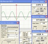
Also, i will be happy to say that the Dx Precision I amplifier (one in Roman Letter please folks), using 64 volts supply and reduced to 62 volts, depending the adjustments you will make, can produce more than 300 watts into 4 ohms and something alike 160 watts into 8 ohms.
Space...maybe your supply voltage is having drops during consumption, during high power peaks, during bass reproduction...if your supply could keep 64 volts without losses, you would have more power than this 128 watts you are informing us...also.... a good idea is to use 5.000uf to each ampere of consumption, and this means that operating with 4 ohms speakers you gonna need 20.000uf to each rail... and this to each amplifier channel...so.... the needed capacitance to a stereo unit operate, the total capacitance needed is 80.000 uf, and i have strong suspections you are not using such values in your home.
This first image is 4 ohms operating...you can see input voltage, the sinus waveform reproduced, upper rail current and lower rail current...operating using 64 volts... simulator results.
regards,
Carlos
In special because have used veroboard....... was lovely to see the fobidden wires.... parallel wires..... this could be a scandall to many forum folks, but killed many myths and beliefs that capacitances, couplings, terrible inductances and all that stuff can ruin (destroy) the sound quality and stability.
As we could see, you are listening a pleasant sonics without any problems.
This means you are teaching things to forum people...important things about parasitic capacitances and inductances that many folks use to say are enormous problems to audio...when my life experience said to me this is not a problem to audio, but can be a big trouble to Radio Frequency transmitters.
It is not the best ideas to use the veroboard, also not a good idea long connections...also not very good parallel and long wires to transistors... this MAY create problems...but not always and the problem is not "that terrible dragon people use to think about such things"!
I do thank you very much...because your contribution to us is enormous.... the construction you have made is "unaceptable" by many friends.... and will not "operate" ..... will "burn".... will "oscilate".... will be a mess.... and was not that way.
I would like to thank you by the kind advertising....your good will....your enthusiasm and help to the virtual big "Dx Corporation"... a Global and Universal Giant Company that only exists in my dreams...in my mind.
Also, i will be happy to say that the Dx Precision I amplifier (one in Roman Letter please folks), using 64 volts supply and reduced to 62 volts, depending the adjustments you will make, can produce more than 300 watts into 4 ohms and something alike 160 watts into 8 ohms.
Space...maybe your supply voltage is having drops during consumption, during high power peaks, during bass reproduction...if your supply could keep 64 volts without losses, you would have more power than this 128 watts you are informing us...also.... a good idea is to use 5.000uf to each ampere of consumption, and this means that operating with 4 ohms speakers you gonna need 20.000uf to each rail... and this to each amplifier channel...so.... the needed capacitance to a stereo unit operate, the total capacitance needed is 80.000 uf, and i have strong suspections you are not using such values in your home.
This first image is 4 ohms operating...you can see input voltage, the sinus waveform reproduced, upper rail current and lower rail current...operating using 64 volts... simulator results.
regards,
Carlos
Attachments
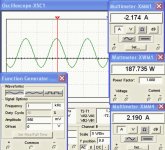
Real world power is always smaller than simulations.
We have always voltage drops into the supply, but not so big as you may have...or.... your voltage may be lower than 64 volts to the output units...also your selection of zener diodes could be smaller than 62 volts.. using 56 volts you gonna loose too much power, but will have better sound... for sure.
The power must be a little bigger than this power you are informing....maybe 145 or 150 watts RMS over 8 ohms.
Here you have a simulation..... i know and many of our friends knows that 128 watts or 165 watts means absolutelly the same to human ears.... this means power and power.... we cannot perceive those differences...the speaker will perceive... also more consumption to the higher power, more heat and stress to output components...but our ears will not perceive...... despite of that...numbers are excelent advertising to people.... each watt advertised means more people building...so...i would be happy to inform those bigger numbers.
regards,
Carlos
Attachments
- Status
- This old topic is closed. If you want to reopen this topic, contact a moderator using the "Report Post" button.
- Home
- Amplifiers
- Solid State
- 128w 8ohms X 2 amp, sound nice, great amp