Having searched the forum I found references to lapping heatsinks but no mention of how effective it is or how flat a surface should be.
I'm servicing an old 500W/chan MOSFET amp. I know that heat was a concern with that model.
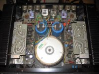
The fets are bolted to an "L" section which is bolted to "U" section, which in turn. has 2 progressivly smaller "U" sections nested inside it. The previous application of thermal grease was unevenly "lumpped" in.
Am I insane to even bother?
edit:-
P.S. I'm talking about the junctions between the lumps of metal, rather than the TO3s themselves.
I'm servicing an old 500W/chan MOSFET amp. I know that heat was a concern with that model.
The fets are bolted to an "L" section which is bolted to "U" section, which in turn. has 2 progressivly smaller "U" sections nested inside it. The previous application of thermal grease was unevenly "lumpped" in.
Am I insane to even bother?
edit:-
P.S. I'm talking about the junctions between the lumps of metal, rather than the TO3s themselves.
Can you omit any of the intervening couplings?
The closer your FETs to the heatsink the better.
A flat and polished surface is desired. But most will settle for a flattish surface finished with 600grit.
All air spaces at the interfaces must be filled with thermal compound and the maximum areas in direct contact the better.
The closer your FETs to the heatsink the better.
A flat and polished surface is desired. But most will settle for a flattish surface finished with 600grit.
All air spaces at the interfaces must be filled with thermal compound and the maximum areas in direct contact the better.
Thanks for the 600 grit number.
Unfortunatly, I can't build it any differently to its design. I might be able to do something about air flow through the sections.
The early model had a more basic heatsink. When I got one the lid had been thrown away to ventilate it. The Mk2 had a more elegant heatsink and more air holes - all signs that there may have been a cooling concern.
That said, I'm sure my Mk2 led a full and happy life before I got it. I'm just trying to enhance. When I get it back together I'll do some Left/right comparrasons. If the rebuilt right side heatsink gets warmer than the left, it must be removing more heat.
Hi,Pbassred said:... someone told me that thermal transfer pads have improved a lot in the last 20 years so I might get more practical results replacing them. I'll still lap between plates though.
the thermal pads have a variation from best to worst of about 10:1 in conductivity.
In the middle comes a typical 0.002inch mica washer with thermal compound to both faces.
A direct metal to metal interface with thermal compound (to exclude the air) will far outperform any thermal pad or other type of conductor.
I have a bit of experience with lapping heatsinks (and CPUs) for overclocking in PC's.
sheet of water paper glued to a mirror...
Overall the increase in thermal performance is small enough to be almost negligible... maybe gain 3C of heat headroom... I would rather look at getting the sinks anodised black (if they are not allready) this will produce a much higher margin in my opinion....
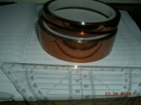
Another idea is to use Kapton (polyimid) Isolation Tape, which will also provide excellent heat transfer due to it's minimal thickness. I've bought those 2 rolls for less than $20 including shipping. Just search the well known internet shopping platform for Polyimid... (from China)
cheers
cheers
Attachments
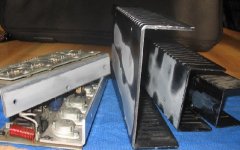
There's only one "commercial" MOSFET power amplifier model with a stacked card deck heatsink arrangement i'm aware of.
IMO, glass mirror grinding and China tape will not hack it, you'll need to beef up the heatsinks.
Either by completely exchanging them, or reinforcing the Matryoshka heatsink by adding aluminum bars inserts to make it more rigid.
IMO, glass mirror grinding and China tape will not hack it, you'll need to beef up the heatsinks.
Either by completely exchanging them, or reinforcing the Matryoshka heatsink by adding aluminum bars inserts to make it more rigid.
I've used clear box tape for insulators with no problem. The tape is clear, and 2 inches wide, so the transistors fit nicely. I just clean the heatsink, and stick on the tape carefully so there's no air under the tape. I grease the transistors, and use a bar to press them down to the heatsink on the tape.
So far it's works good with good thermal performance.
So far it's works good with good thermal performance.
- Status
- This old topic is closed. If you want to reopen this topic, contact a moderator using the "Report Post" button.
- Home
- Amplifiers
- Solid State
- Lapping heatsinks?