Hey guys, i found this circuit somewhere on the web and decided to build it, so i got all the parts and put it together, however instead of amping my signal like it should. all i get is a loud buzzing through the speaker, kind of like mains hum.
there are a few points of concern but i cant seem to figure it out.
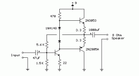
i've attached the circuit diagram for you guys to look at:
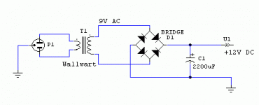
1. im using a 9v wall-wart. it emits 9v AC. the circuit has two diodes which im assuming is a bridge rectifier, converting ac to dc. is the fact that im using AC instead of DC going to be a problem?
2. instead of using the prescribed 2n2905A transistor for the PNP, i used a 2n2907 instead, would this be a problem?
3. lastly, just wondering if this circuit has any errors?
Attachments
The good old 3 transistor complementary amp!  You can make one work well with enough tweaks.
Here's some tips for a newbie to get one working.
The Hardest part IMO of making an amp is bias, and hot transistors blowing up from first making it can be frustrating. I'll offer some help to make it easier, because it took me a long time to learn it by myself.
I'd recommend using big power amp transistors and a heatsink if you can get them. They are harder to blow up then little ones.
1. Put a variable resistor (POT) connected across the diodes where they connect to the base of each transistor. Set it to 0 ohms for no bias to start with.
2. The output where the 3.3 ohm resistors connect HAS to measure exactly HALF of the total DC voltage, each transistor splitting it evenly. This is the key to making the amp work good. Measure this with a good meter to find out.
3. Try another POT +1K in series in place of the 5.6K resistor and adjust the resistance until the output voltage of amp is in the center. Then replace with resistor that matches the resistance.
4. Now adjust the bias POT across the diodes and slowly adjust until output stage pull no more than 50mA-75mA or 15-23mV across 3.3ohm resistors. If that's too hard, then just adjust until transistors get a little warm but not hot.
5. Add a 100-200pf cap across the amp's input and ground, and add another one to the base-collector leads of the input transistor. I'd also recommend adding a 0.1uf cap in series with a 10 ohm resistor from the output to ground.
- Status
- This old topic is closed. If you want to reopen this topic, contact a moderator using the "Report Post" button.
- Home
- Amplifiers
- Solid State
- 3 transistor amp

