The outputs running warm probably normal. There does not appear to be any thermal compensation (a vbe multiplier ) which is most unusual so for this reason I would not experiment with altering the bias current, but it may be worth confirming that 9mv across the output resistors (as shown on circuit) R41/42 is somewhere near when it's been on a while. No load attached for this measurement. Q8, 5 seconds before you have to take your finger off, thats pretty hot, these are the kind of conditions that cause intermitant faults in semiconductors. Some transistors seem to be more prone than others, even though they are officially well within their ratings. Video output transistors and line driver transistors were favorite for this. Switch off and they read O.K. but fail, usually B-E going open circuit when running. Q8 doing this would give your fault by the way.
Any one reading this and seeing me mention OpAmps is thinking, oh no hear we go again, he's going to say OPA2604 for duals and OPA604 for singles. Well you're right . Actually I bet the TLO72 and TLO71 would work well here, and in the preamp of course. Plus they are readily available, cheap, and they sound really good, better than most would give credit for these days.
Edit just a thought fault finding if you only have a meter and no scope. Rig up an LED across a bridge rectifier and feed the bridge through say 6.8 Kohm. Connect across speaker output and LED will light if DC appears of either polarity.
Any one reading this and seeing me mention OpAmps is thinking, oh no hear we go again, he's going to say OPA2604 for duals and OPA604 for singles. Well you're right
. Actually I bet the TLO72 and TLO71 would work well here, and in the preamp of course. Plus they are readily available, cheap, and they sound really good, better than most would give credit for these days.Edit just a thought fault finding if you only have a meter and no scope. Rig up an LED across a bridge rectifier and feed the bridge through say 6.8 Kohm. Connect across speaker output and LED will light if DC appears of either polarity.
In fact, further to this, the main power transistors for the left channel do appear to be running a lot hotter for the left channel (the dodgy one) than the right channel, so perhaps there's still a problem lurking.
I can leave my fingers on the heatsink for the right channel for several seconds without a huge amount of discomfort, but less than a second for the left heatsink (I think I need a temperature probe rather than my fingers!). This is after the amp has been running for a couple of hours.
I'll check whether it's 9mV across R41/R42...
Wayne
Worth checking, read my edited post above re LED. The bias setting is going to be "critical" I think on this design. I think it will vary quite a bit so dont get hung up over the fact you set it to 9mv and a few minutes later it's at 12 say, thats just the way it is. Without thermal compensation the output stage can suffer thermal runaway, the outputs heat up vbe drops , it conducts more gets hotter and so on. Keep tweaking the pots on both channels untill it settles at around 9mv, and from cold this may take 30mins or more.
Reread your post, 1 second, thats way to hot. With it being an old amp the preset RV1 may be dickey. With the amp off give it a squirt of wd40 ( not a squirt a drip ) and spin it to and fro a few times, or better still replace. To make sure no disasters happen put the bulb back, and readjust. You must start with the pot at MINIMUM resistance as this give the lowest bias current.
I'm just waiting on the 30 mins to let it really warm up before doing some proper voltage checks.
After 10 minutes, the voltage drop for the right channel (across TP14/TP15) gives 25mV, but for the left channel (TP12/TP13) it's 90mV, so they're both quite a bit out at the moment.
I'll wait for the amp to really warm up before tweaking anything.
That's with the speakers disconnected while testing the voltage drop.
Well, so far so good... I've switched it off, given both RV1 and RV101 a good swizzle both ways, to clear them, and reset to just under where they were.
The power transistors are now running pretty cool, and I've tweaked them both to get 9mV as close as I can for now - I'll double-check it later once it's been running for a while.
R40 and Q8 (and R140 and Q108) are both still running warm, however. Too hot to hold a finger on for longer than a few seconds.
Indeed, something more was definately wrong. Was upstairs for half-an-hour, while the hi-fi playing away downstairs.
Left output fuse has blown, and (presumably prior to the fuse blowing), the woofer of the left speaker has blown. In addition, the right channel has started to get the scratchy sounds.
Grrr...
Anyone know a good place for a replacement woofer for a Celestion 5 speaker?
Left output fuse has blown, and (presumably prior to the fuse blowing), the woofer of the left speaker has blown. In addition, the right channel has started to get the scratchy sounds.
Grrr...
Anyone know a good place for a replacement woofer for a Celestion 5 speaker?
Oh dear, thats a shame, this is what happens when you leave speakers connected to an amp with a DC offset problem. This is what I was hoping to avoid by suggesting the LED to indicate if there was a problem.
As to a replacement speaker, I don't know I'm afraid. How old are the speakers ?
Well anyway I hope it hasn't put you off the DIY Audio. Are you going to persevere with the amp, I think you should. We have all been there, it's part of the learning curve. I am reasonably sure from what you said earlier about the excessive current that this could well have been the problem all along. The amp has been going into thermal runaway. See if it still works first of all.
Regards Karl
I don't think I'll quite throw the amp out yet... I'd like to see if I can get it working, but as I have a replacement amp now anyway, so it's probably less pressing. I just don't know at what point to decide that the amp is working properly... I was regularly checking the voltages across the terminals and across R41/42 and tweaking RV1 just a fraction every 15 minutes or so, and all seemed to be fine... then extended it to 30 minutes, etc. and all seemed fine and dandy.
The speakers are about as old as the amp - 15 years, so they've had a good life. Just a bit of a pain (and probably will be costly to replace). I've not actually been actively looking around at hi-fi stuff now for a good few years, so I'm going to have to start reading What Hi-Fi again to find some suitable replacement speakers and go and spend some time listening to some. All the ones I knew about (i.e. Mission 780's, etc. are all out-of-date now).
As you say, this has been a bit of a learning experience (Still like the trick with the lamp on the power supply input - I might actually make up an IEC cable with the light in series - saves soldering onto the fuse inside the amp!).
My main concern now, really is that once I think it's fixed again... I might just end up blowing some more speakers. Just don't know how well I'll trust it to actually be fixed!
Wayne
For good budget gear check out www.richersounds.com
Back to your Arcam, as I hinted at earlier I found it very strange that there was no thermal compensation but there isn't. This makes the setting of RV1 very critical. Its probably easier to solder some wires to TP12/13/14 &15 and connect these to the meter. This way you can keep an eye on the readings while tweaking the pot. Did the pots feel "loose" might be worth replacing. Do all the output transistors share a common heatsink. If so the two channels will interact, as one warms up, it affects the other.
See how you get on, if you want to know how to wire the LED and bridge up I can draw it, all bits from Maplin, and if you want to try it with speakers fit much smaller fuse, even as low as 100ma, just don't play it to loud to begin with.
Yes, I know of Richer Sounds - we have a store here in Guildford even! Once I know what I want, I'll check out their prices - just need to do a bit of research and listening first!
The pot for the left channel did feel loose, compared to the right channel - the right channel is pretty stiff to move.
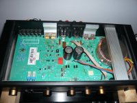
Each pair of output transistors for a channel shares the same heatsink (i.e. Q13/Q14 are on one heatsink and Q113/Q114 are on another). Each of these heatsinks is on either side of the speaker terminals, and is bolted to the metal casing at the rear. The lid screws into the two heatsinks, so they are kind of joined... but not a lot! Actually... see the picture attached (the blocks of wood are because I'm waiting on some new rubber feet at Maplin - the old ones had turned into a gooey mess - heat related, maybe!)
I think I know how to wire the bridge up - four diodes for the bridge and stick that in series with the resistor and LED. Alternatively, I was just going to wire a couple of LEDs up in parallel (with different polarity) and stick the resistor in series with this. Same thing, really, just one LED will light or the other, depending on which way round the DC voltage is.
The pot for the left channel did feel loose, compared to the right channel - the right channel is pretty stiff to move.
Each pair of output transistors for a channel shares the same heatsink (i.e. Q13/Q14 are on one heatsink and Q113/Q114 are on another). Each of these heatsinks is on either side of the speaker terminals, and is bolted to the metal casing at the rear. The lid screws into the two heatsinks, so they are kind of joined... but not a lot! Actually... see the picture attached (the blocks of wood are because I'm waiting on some new rubber feet at Maplin - the old ones had turned into a gooey mess - heat related, maybe!)
I think I know how to wire the bridge up - four diodes for the bridge and stick that in series with the resistor and LED. Alternatively, I was just going to wire a couple of LEDs up in parallel (with different polarity) and stick the resistor in series with this. Same thing, really, just one LED will light or the other, depending on which way round the DC voltage is.
Attachments
Grrr... just thought I'd do a quick test - switch the amp on with the probes in the speaker socket (voltage -37V) and twiddle RV1. I figured that if RV1 is a bit dodgy, then a quick twiddle should would make a good contact and 'fix' the problem - indicating that that RV is in need of replacement.
Guess what... voltage at the speakers is now 0V, not -37V without twiddling it.
The wonders of intermittent faults!
Guess what... voltage at the speakers is now 0V, not -37V without twiddling it.
The wonders of intermittent faults!
- Status
- This old topic is closed. If you want to reopen this topic, contact a moderator using the "Report Post" button.
- Home
- Amplifiers
- Solid State
- Arcam Alpha 3 Left Channel broken...