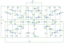
This is an amp design that I have been working on for a while. I am now at a point where, I think, it is good enough to post on diyAudio.com
It ticks most of my requirements for a good audio power amplifier:
Wide Open Loop Bandwidth (>20kHz)
Low-ish Distortion
No more than 2 Stage design
Stable while clipping
What Attributes I like about this amplifier:
Wide Bandwidth
Medium Open Loop gain
Very Stable
Each Quadrant has its own feedback loop, If any pair of quadrant clips and the feed back loop goes open then there are 2 more feedback loops to keep control.
Good common mode rejection.
I hope you all like it.
If there is any critiques or improvement let me know
Cheers
Tim
Attachments
Doubtful, since the feedback loops are a voltage divider with the input signal. The drive signals for M67/M68 will be unequal in magnitude. I have built a circuit that will convert SE signals into BL, with gain and DC control. Maybe a bit complex but it works very well. Also, there is these if you have vendetta against discrete circuits.
EWorkshop1708 said:One amp to get a BTL output, cool.
Question, can you drive this amp with a regular unbalanced input source and still get the BTL output?
It will be fine. All that will happen is 1/2 of the cycle will clip earlier than the other.
Cheers
Tim
Tim, may I suggest to use more data points on these (say 200/decade)? Although not very likely here, the sim could have missed a high Q-resonance just before the roll-off.
Your plots are with plain resisitive load, I guess, no series L//R and no zobels. What happens if you hook a load cap (stepping it from 1nF to 10uF, 1-3-10 steps)?
For testing simmed stability I like to use a step voltage source of 100mV or so, with 10ns rise time, putting it into various places into the circuit (not only at the input) and then look at any overshoot/ringing, also at various places, not only the output (sometimes one can invoke hefty CM ringing which doen't show up at the output).
More elobarate stuff is the Tian method of plotting open-loog gain bode plots, which also provides much insight wrt small signal transfer function.
- Klaus
Hi KSTR
Thanks for your help.
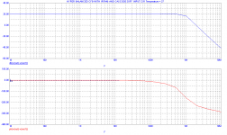
You are right there is a resonant peak at about 1MHz and this is highlighted when I simulated the AC response with a 1uF across the output (and no series resistance).
I tried a quick brute force fix, by increasing my 3pF compensation capacitors to 30pF, which does stabilise the amplifier into 1uF but it reduces the open loop bandwidth and so increases the higher order harmonics in the distortion.
I suspect the culprit for this resonance is the input cascode, I think it is 2 mosfets too many. I have had similar performance without them but I had to use lower value feedback resistors to get the same closed loop bandwidth. Maybe I will try JFETs instead of the input mosfets and get rid of the cascode.
I ran out of time, this morning, to try anything else so I will look at the design again in the evening.
Cheers
Tim
Thanks for your help.
You are right there is a resonant peak at about 1MHz and this is highlighted when I simulated the AC response with a 1uF across the output (and no series resistance).
I tried a quick brute force fix, by increasing my 3pF compensation capacitors to 30pF, which does stabilise the amplifier into 1uF but it reduces the open loop bandwidth and so increases the higher order harmonics in the distortion.
I suspect the culprit for this resonance is the input cascode, I think it is 2 mosfets too many. I have had similar performance without them but I had to use lower value feedback resistors to get the same closed loop bandwidth. Maybe I will try JFETs instead of the input mosfets and get rid of the cascode.
I ran out of time, this morning, to try anything else so I will look at the design again in the evening.
Cheers
Tim
- Status
- This old topic is closed. If you want to reopen this topic, contact a moderator using the "Report Post" button.
- Home
- Amplifiers
- Solid State
- The New Hyper Balanced Amplifier