Hi Electrician, thanks for all that work! So if I replace R5 with a 470k resistor and C3 with a 470pF capacitor (according to your schematic of course) then I should get the response that you posted most recently (which looks great btw!)
Cool, what about the mid control though. Is there a way to model and refine the values used there too?
Actually, I'm installing matlab as we speak so if you could be kind enough to explain how you actually obtained the transfer function in the 1st place then I could do it myself in matlab and inculde the mid control too!
Thanks again.
PS Where did you get Mathematica from? I've used matlab before so I'm probably better off sticking to that though!
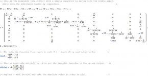
I just did a conventional nodal analysis using the admittance matrix of the circuit. To avoid having to use Modified Nodal Analysis, I dealt with the opamp in a slightly non-standard way.
You just write down the admittance matrix, letting node 1 be the input and node 8 be the minus input to the opamp. Call this admittance matrix Y; compute its inverse and call that Z. Then the transfer function to node 8 is as given in the attachment. The node numbering is as shown in the next post where I also include the mid-band function.
You can see a couple of entries at elements (4,8) and (7,8) of the matrix; this takes care of the feedback from the opamp. Then multiply the transfer function to node 8 by the gain of the opamp, -A, and you have the TF to the opamp output.
Then just use this transfer function (with A set to a big number; I used 10^10) to plot the response versus frequency for various values of the Kb and Kt (potentiometer rotation) coefficients.
Attachments
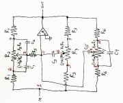
Here's the schematic I used for the analysis of the tone control circuit. The node numbering for the bass/treble only version is the same as this except that nodes 8, 9 and 10 are missing and node 11 was node 8.
In the next post, I'll give the admittance matrix for the version with mid-band. It's an 11x11 matrix, and solving it symbolically begins to slow Mathematica down. It takes 8 seconds to invert the matrix on a fast computer. The inversion usually takes well under a second, so to take 8 seconds means the result is massive. I won't post the result because it's several pages of algebraic expression. Fortunately, it's not necessary to see it in order to use it.
You wanted to know where I got Mathematica. It's a product of Wolfram Research, and I got it at work several years ago.
Attachments
Here's the admittance matrix for the mid-band circuit (plus bass and treble, of course).
This forum won't let me post an image this wide, so I put it on:
http://img2.freeimagehosting.net/uploads/22a3fc900b.gif
You should be able to view it there.
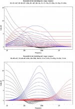
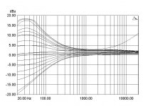
I've posted the response of the full circuit with mid-band here. I had to re-size the image to keep it under the posting limits on this forum and it got a little jagged looking, but I think it's still useful.
The top set of curves is for the values you gave in your post of the full mid-band version; I think I got all the values right!
The black curves are the bass response, blue is the mid-band and red is the treble response. The treble response is not quite what one would want!
The lower set of curves are the responses with the values changed as shown just below the title. The treble response is still a little reduced, but I'll let you fiddle with the values to get it better.
This forum won't let me post an image this wide, so I put it on:
http://img2.freeimagehosting.net/uploads/22a3fc900b.gif
You should be able to view it there.
I've posted the response of the full circuit with mid-band here. I had to re-size the image to keep it under the posting limits on this forum and it got a little jagged looking, but I think it's still useful.
The top set of curves is for the values you gave in your post of the full mid-band version; I think I got all the values right!
The black curves are the bass response, blue is the mid-band and red is the treble response. The treble response is not quite what one would want!
The lower set of curves are the responses with the values changed as shown just below the title. The treble response is still a little reduced, but I'll let you fiddle with the values to get it better.
Attachments
Thanks again! I've simulated my circuit using those values you suggested and the mid response has certainly 'tightened' up (less Q which is good ") , the treble was boosting high frequencies before (7k and above) but it boosts them a bit more with those new values now. Although - it wasn't boosting those low frequencies before as your freq. reponse suggested - weird! The bass seems to have a steeper roll-off and a better peak at those lows. Cool.
, the treble was boosting high frequencies before (7k and above) but it boosts them a bit more with those new values now. Although - it wasn't boosting those low frequencies before as your freq. reponse suggested - weird! The bass seems to have a steeper roll-off and a better peak at those lows. Cool.
My circuit is breadboarded atm so I'll change the vales and measure its frequency response later - I'll let you know how it all goes.
How did you treat the op-amp in your circuit analysis btw? I really would like to try and obtain an expression for the transfer function of the circuit myself but I don't know much about admittance matrices, and it's been a while since I did some nodal analysis last! (I think it included using kirchoff's and ohm's laws for impedances, summing them clock-wise or anti-clockwise etc ? ? ) If you have any advice on, or ideas as to where some good advice may be located, nodal analysis & admittance matrices then please do pass this info on!
PS Is it not node 11 that's the input to the inverting input of the op-amp?? - As opposed to node 8 which you mentioned in a previous post
Cheers
, the treble was boosting high frequencies before (7k and above) but it boosts them a bit more with those new values now. Although - it wasn't boosting those low frequencies before as your freq. reponse suggested - weird! The bass seems to have a steeper roll-off and a better peak at those lows. Cool.My circuit is breadboarded atm so I'll change the vales and measure its frequency response later - I'll let you know how it all goes.
How did you treat the op-amp in your circuit analysis btw? I really would like to try and obtain an expression for the transfer function of the circuit myself but I don't know much about admittance matrices, and it's been a while since I did some nodal analysis last! (I think it included using kirchoff's and ohm's laws for impedances, summing them clock-wise or anti-clockwise etc ? ? ) If you have any advice on, or ideas as to where some good advice may be located, nodal analysis & admittance matrices then please do pass this info on!
PS Is it not node 11 that's the input to the inverting input of the op-amp?? - As opposed to node 8 which you mentioned in a previous post
Cheers
measured response
I measured the circuit with those new values - although adimttedly there was no 22nF so I used a 20 and no 5nF capacitor so I used a 4.7nF one.
The response is much better than before. The bass pot was affecting some frequencies that it shouldn't have been and that's been rectified. The mid control seems less tighter than I expected and its' peak is a bit flat when it's at full boost. Other than that though it all looks rather good!
I used a breadboard for the circuit and PRISM SOUND to measure its' response. A TL084CN op-amp was used in the circuit.
I'm about to create a PCB for the preamp circuit you've helped me with but I'm also going to incorporate an audio transformer so that I can have an XLR (suitable for D.I.) output too. I'm going to research transformers next...
Attachments
jenks said:PS Is it not node 11 that's the input to the inverting input of the op-amp?? - As opposed to node 8 which you mentioned in a previous post
Cheers
Referring to the schematic in post #24, for the matrix which applies to the circuit WITHOUT a mid control, the matrix is 8x8 and the opamp inverting input is node 8. For the case WITH a mid control, the matrix is 11x11 and the numbering is as shown in the schematic.
Have a look at this web page:
http://www.inictel.gob.pe/publicaciones/rvargas/red-activa.htm
The treble control shown there is a slightly different topology than the one we've been discussing. I've always wondered of there is much difference in the behavior of the two. You've got me interested again in the question. I'll do up an analysis of the second one and compare to the first.
I've sent you a private email through the forum.
In order to do the transfer function did you firstly combine some of the capacitors and potentiometers like so:
C1 and (1-Kb)R2 in parallel and then C2 and KbR2 in parallel as well so that you can effectively separate the capacitors with the potentiometer into two components that lie in series with R1?
C1 and (1-Kb)R2 in parallel and then C2 and KbR2 in parallel as well so that you can effectively separate the capacitors with the potentiometer into two components that lie in series with R1?
jenks said:In order to do the transfer function did you firstly combine some of the capacitors and potentiometers like so:
C1 and (1-Kb)R2 in parallel and then C2 and KbR2 in parallel as well so that you can effectively separate the capacitors with the potentiometer into two components that lie in series with R1?
I think the answer is yes.
I should have shown the potentiometer as two resistors, rather than as one. For the purpose of the analysis it's treated as two, split at the arrow, as you have described.
- Status
- This old topic is closed. If you want to reopen this topic, contact a moderator using the "Report Post" button.
- Home
- Amplifiers
- Solid State
- transfer function