Hi,
I am trying to get to the bottom of a small problem that I am hoping some of the smart bods on here will be able to assist with.
I am building an OPA627 buffer to go in my pre-amp which will drive my ChipAmp.com (LM3886) power amp. I have collected together the parts based on the information on this website:
http://www.platenspeler.com/diy/preamps/uk_gainchooser_3.html
What I am stuggling with is whether I can use the polypropylene capacitors I have for decoupling the op-amp as I couldn't find any ceramics as suggested (though I have now found the 0.1uF, but not the 4.7uF)? Are the capacitors I have too big and mounted too far away from the chip to work effectively?
I have attached a picture of the layout to give you an idea.
Attachments
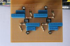
Holy cow! Those caps are HUGE!!!!
To decouple the power supply at the chip power inputs, you don't need anything even CLOSE to that voltage rating (and I have no idea what the rating is, but it is overkill!). What you have shouldn't cause a problem, but they are overkill. You seem to have them pretty close to the power supply pins, so you should be OK, but the next time you are in an electronics store or making an order, just buy a bag of 100V 0.1uF ceramic caps! You WILL use them.
I am not really sure what you are talking about with the 4.7uF caps, but you should be fine using an electrolytic or tantalum for that size instead of a ceramic or film. The ceramic or film would be physically quite large at that voltage/capacitance rating. If it is in parallel with the ceramic/film decoupling cap, then you will definitely be fine with tantalum or electrolytic.
David
Yes, if you don't have anything smaller but plain 0.1uF/63 V polyester would be just fine.ianpengelly said:What I am stuggling with is whether I can use the polypropylene capacitors I have for decoupling....
I get good results with small 0.47uF Panasonic film caps for bypassing, and even that's probably more capacity than needed. The real trick is keeping them close to the op-amp. I'd isolate the outputs with 100 ohms, not 10 as per the original design. I also have to wonder about those resistors- are they carbon films? Seems an odd choice to use with such an expensive op-amp.

Somewhere upstream there should be more capacitance, but the 627 is a 16 MHz op-amp, and needs *local* bypassing appropriate to its speed. No electrolytic, even an Oscon, is really suitable. I'm not saying it won't work, or will break out into gross oscillation, but you really need a small ceramic or film, close to the pins, to get all the performance the part is capable of. The National parts like LME49710 are even faster (55 MHz) and the same caution applies. The part doesn't care that it's in an audio circuit- it needs low impedance supplies at the frequencies where it has gain.
Re: Re: OPA627 Buffer Based Preamp
Not that I have a preference, but why do you recommend polyester over ceramics? I'll use either without thinking just based on what I have lying around, but if I am ordering parts, I have always defaulted to ceramics. Any insights?peranders said:
Yes, if you don't have anything smaller but plain 0.1uF/63 V polyester would be just fine.
Re: Re: Re: OPA627 Buffer Based Preamp
Many thanks for all the input so far!
Quite, are there any addvantages other than they tend to be much smaller?
I am pleased the layout will work with the caps I have, at least they aren't going to be wasted.
What should I do with the op-amp trim connections? Should these be grounded or left floating if I am not going to use them?
Conrad, when you say you should isolate the outputs with 100 ohms instead of 10, are you refering to the signal outputs from the op-amp, and if so why?
Many thanks for all the input so far!
dfdye said:Not that I have a preference, but why do you recommend polyester over ceramics? I'll use either without thinking just based on what I have lying around, but if I am ordering parts, I have always defaulted to ceramics. Any insights?
Quite, are there any addvantages other than they tend to be much smaller?
I am pleased the layout will work with the caps I have, at least they aren't going to be wasted.
What should I do with the op-amp trim connections? Should these be grounded or left floating if I am not going to use them?
Conrad, when you say you should isolate the outputs with 100 ohms instead of 10, are you refering to the signal outputs from the op-amp, and if so why?
I've looked at lots of caps on a vector impedance meter, and for serious RF you're better off with physically tiny ceramics. Still, the film caps are good to very high frequencies- my guess is they're limited more by physical dimensions, than by material properties. As soon as you have 1/4 - 1/2 inch of lead length, you lose the properties of either one. Films seem to give very good results with typical audio op-amps.
I prefer to isolate cable capacitance with 100 ohms (ok, 50-200) for stability reasons. High performance, high bandwidth op-amps aren't that stable into capacitive loads, especially at low gains, and I don't detect any sonic penalty. Try various values and see what you hear. Advice from fools on the 'net is always risky
I prefer to isolate cable capacitance with 100 ohms (ok, 50-200) for stability reasons. High performance, high bandwidth op-amps aren't that stable into capacitive loads, especially at low gains, and I don't detect any sonic penalty. Try various values and see what you hear. Advice from fools on the 'net is always risky

It surely has been said before.... still worth repeating:
Either bypass with one single good quality cap (any modern eletrolytic is fine), or with a high ESR / low ESR combo (1...10uF/35V tantal + 10...100nF ceramic), close to the pins and directly to GND. Even better, isolate the supply pins with small resistors, and additionaly bypass directly across them. See:
http://www.analog.com/UploadedFiles/Application_Notes/135208865AN-202.pdf
To recha the full potential of the 627, one might consider biasing it into class A, further impedance matching at the inputs is a good thing (would be tricky here, with the stepped input divider). OTOH, for a plain standard GC this is probably overkill (as is the 627 itself, IMHO).
In a controlled application I'd say that those 10 Ohms isolating R is OK. Again, one would try to choose it accordingly to get impedance matching among the GC input pins, assuming an non-inverting GC.
- Klaus
Klaus,
Thank you for the information. I'll have a look at the link you sent and see if I need to make any changes, or keep it in mind for next time round.
I don't believe the 627 is overkill for a gainclone, at the end of the day rubbish in = rubbish out. The DAC that feeds the beffer is a TAG DAC20 and this uses the 627s in its output stage, so it seems sensible to continue this trend. Plus there is always the possibility that the GC gets replaced by something else at a later date.
ianpengelly said:So, is anyone able to shed light on what to do with the trim connections? Do they need to be connected to ground or can they be left floating?
You MUST read the datasheet!
Trims are invariably part of the input differential pair biasing, with the trimpot connecting to V+ (and sometimes V-).
Grounding them will usually play havoc with the amp and it probably will not function.
I should have made it clearer that I was agreeing with him!
Data sheet: here
Page 8 shows the trim, although it does not explicity explain what to do if trim not used.
ianpengelly said:Cliff,
Thanks for the input, but I couldn't find any information on the datasheet relating to the standard procedure for the trim connections.
At Klaus's advice they will be left floating.
Data sheet: here
Page 8 shows the trim, although it does not explicity explain what to do if trim not used.
Unused trims are to be left open, with any opamp I'm aware of. And those are inputs (one can make use of that, sometimes) and somewhat sensitive to stray noise pickup, just like the supply pins are.
Er, with overkill I meant the price/performance ratio of the 627, which is a bit too high for my likings. Of course there is nothing wrong with the general idea to keep any links in the chain as strong as possible. OTOH, some people tend to use not mutliples of the same part repeatedly in the signal chain, because this might emphasize the specific sound of the part (if any, that is). Which is sometimes just what we want. All very subjective, YMMV.
- Klaus
Ahh, sorry I see what you mean... yes they are very expensive, however, I picked mine up for a fairly reasonable price, though certainly not as cheap as some of the Analogue Devices equivalents.
On your second point, that could also be true, I am hoping the 627 is neutral enough not to affect things too much by adding another one in the signal path.
Thanks!
On your second point, that could also be true, I am hoping the 627 is neutral enough not to affect things too much by adding another one in the signal path.
Thanks!
Back for more?
Well I started this thread about 18 months ago and my little project ended up in the loft after I got no where with it... it had nothing to do with the fact that I was being a complete idiot and had the chips in the wrong way round!
So, I dug it out again last weekend and decided to start from scratch with a simpler design and one using slightly more manageable capacitors, as kindly suggested within this thread. On the basis that I wasn't sure if the 627s survived being maltreated I picked up some OPA134s to do some testing with and get things rolling.
I just need to get my RAW file convertor installed and I'll can bring you up to speed on my latest journey!
- Status
- This old topic is closed. If you want to reopen this topic, contact a moderator using the "Report Post" button.
- Home
- Amplifiers
- Solid State
- OPA627 Buffer Based Preamp