ZOBEL OR NO ZOBEL ?????
AND WHY ????
some have exactly after the output of the amlifier the well known 0.1 mfd cap plus 100 R resitor to ground and then followed by one resistor in parallel with a coil .....
some others have first the network coil resistor then the 0.1mfd cap and resistor to ground
once i ve seen coil and resistor network and then from the out of the RC a 0.1 mfd to ground ....
coments about the best technic and also the best arangement between all that is very welcome ......
been working with a mosfet and seemed to play better with 0.1mfd +100R resistor to ground followed by a coil but with no resistor in paralel with it tryied 1R,2R,10R,100R..... but after all sounded better withoutany resistor ...just a coil ...any comments ????
Even Self seems not to be able to explain precisely why the universally optimum values are 10 Ohms and 0.1uF for the Zobel network .
However, I can tell you from practical experience that you should always use a Zobel network.
It should run from the output node of the amp - so directly at the junction of the emitter degeneration resistors in a typical EF bipolar output stage to the main filter capacitor 0V junction.
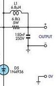
Don't forget the out put inductor either - 2-5uH with 2.2 Ohm 3W resistor in parallel.
If you leave out the Zobel network, you are likely to see parasitic HF oscillations in the 2-5MHz range. If you omit the output inductor, you can expect oscillations of 200Khz to 500KHz with a capacitive load - and real world capacitive loads come from typical speaker cables and speakers themselves.
The two simple techniques - Zobel + output inductor networks - will go a long way to creating a stable, reliable amp.
However, I can tell you from practical experience that you should always use a Zobel network.
It should run from the output node of the amp - so directly at the junction of the emitter degeneration resistors in a typical EF bipolar output stage to the main filter capacitor 0V junction.
Don't forget the out put inductor either - 2-5uH with 2.2 Ohm 3W resistor in parallel.
If you leave out the Zobel network, you are likely to see parasitic HF oscillations in the 2-5MHz range. If you omit the output inductor, you can expect oscillations of 200Khz to 500KHz with a capacitive load - and real world capacitive loads come from typical speaker cables and speakers themselves.
The two simple techniques - Zobel + output inductor networks - will go a long way to creating a stable, reliable amp.
Yes it is good advice to add the Zobel, and the output choke.
However some designs do not need one or the other (yet to see one with neither)
Current feedback doesn't always need a zobel network, and amplifiers can be stable without a choke. Don't forget the parallel resistor on the choke if you have one, and it dampens the ringing caused by the choke into reactive loads.
Also a zobel style circuit before and after the choke is sometimes needed on MOSFET output stages as they can need additional control at high frequencies due to their speed and tendancy to parasitic oscillation.
Less is more when it come to series componenets in the signal path. But Zobels should be transparent-ish. Remember to make sure the resistor can take the power of the highest frequency the power amp input filter will pass.
I'll jump in with an opinion:
The zobel can go before the choke. It can go after in the form of just a capacitor across the output if the chokes output resistor is the right value for the zobel.
How ever if you're playing with MOSFETs, slap it right next to the devices.
Without a damping resistor the choke will resonate with large capacitive loads, with huge overshoots on squarewaves. Not good if you're using electrostatics, or esoteric speaker cables.
Try a 10kHz squarewave and attach 8ohm load in parallel to 100n, then 2uF and watch the output with a choke with and without the damping resistor. The resonance gets much less, but still present.
Yes it is good advice to add the Zobel, and the output choke.
However some designs do not need one or the other (yet to see one with neither)
Current feedback doesn't always need a zobel network, and amplifiers can be stable without a choke. Don't forget the parallel resistor on the choke if you have one, and it dampens the ringing caused by the choke into reactive loads.
Also a zobel style circuit before and after the choke is sometimes needed on MOSFET output stages as they can need additional control at high frequencies due to their speed and tendancy to parasitic oscillation.
Less is more when it come to series componenets in the signal path. But Zobels should be transparent-ish. Remember to make sure the resistor can take the power of the highest frequency the power amp input filter will pass.
However some designs do not need one or the other (yet to see one with neither)
Current feedback doesn't always need a zobel network, and amplifiers can be stable without a choke. Don't forget the parallel resistor on the choke if you have one, and it dampens the ringing caused by the choke into reactive loads.
Also a zobel style circuit before and after the choke is sometimes needed on MOSFET output stages as they can need additional control at high frequencies due to their speed and tendancy to parasitic oscillation.
Less is more when it come to series componenets in the signal path. But Zobels should be transparent-ish. Remember to make sure the resistor can take the power of the highest frequency the power amp input filter will pass.
Hi,
A zobel is required because the gain of your output stage is very much dependent of the load connected to it. Normally, you dimension your output stage to give appropriate gain at 8 ohms load, but in reality, the load of an actual loudspeaker (plus cable) usually is inductive at ultrasonic frequencies. Unless you have a very limited bandwidth in the output stage, the gain of the output stage will typically rise with rising frequency due to this inductivity, and as a result, the open-loop gain of your amplifier is out of control. This compromises the gain and phase margin, and may make your amp unstable.
Therefore, a zobel is included to make sure the output sees a resistive load at high frequencies, keeping the open loop gain within bounds.
The output inductor is simply there to guarantee your load going inductive at HF. If you drive (long) cables, certain filter topologies, or a piezo tweeter, the load doesn't turn inductive at high frequencies, but capacitive. Here, the zobel scheme falls apart, so you include a series inductor in the amplifier after the zobel, to keep the scheme working properly.
Finally, the resistor parallel to the L is there because, effectively, a series-resonance circuit is formed by the combination of the output inductor and a capacitive load, which forms a short at resonance. The resistor in parallel with the inductor is there to reduce the Q of this circuit, and as a result prevent the short from occurring.
The optimal values for these components require careful dimensioning, and this is not a trivial excercise. But if the values you come up with experimentally work for you, and if the amp doesn't get hotter than normal, and if you don't see an oscillation with the scope, I'd just say leave them in, close the case and have a beer...
Jurgen
Bonsai said:Even Self seems not to be able to explain precisely why the universally optimum values are 10 Ohms and 0.1uF for the Zobel network .
However, I can tell you from practical experience that you should always use a Zobel network.
It should run from the output node of the amp - so directly at the junction of the emitter degeneration resistors in a typical EF bipolar output stage to the main filter capacitor 0V junction.
Don't forget the out put inductor either - 2-5uH with 2.2 Ohm 3W resistor in parallel.
If you leave out the Zobel network, you are likely to see parasitic HF oscillations in the 2-5MHz range. If you omit the output inductor, you can expect oscillations of 200Khz to 500KHz with a capacitive load - and real world capacitive loads come from typical speaker cables and speakers themselves.
The two simple techniques - Zobel + output inductor networks - will go a long way to creating a stable, reliable amp.
There are no generally optimum values for a Zobel RC, it's just a high frequency load for the amplifier. 10 ohms and 0.1uF are just convenient enough values that work in most instances. The only requirement is that the Zobel RC is a sufficiently 'heavy' load for the amplifier.
Also, there are many design factors involved, but it isn't always particularly difficult to compensate a design for unconditional stability without a Zobel RC.
One of the reasons for adding a series inductor//resistor is to prevent the amplifier from detecting AM radio signals. But when your amplifier doesn’t receive Radio Russia or whatever, can one conclude after reading the previous posts, that an amplifier doesn’t need a series inductor//resistance when it passes the following test?
Load the amplifier with an 8 Ohm load and a capacitor in parallel, ranging from a few pF to let’s say 2uF (I have a decade capacitor). Apply a 10 kHz square wave at the input and vary it’s amplitude for each chosen capacitor, from mV’s till onset of clipping at the output. Observe that, apart from some ringing at higher capacitances, no oscillations do occur.
What do you guys think? Especially in High End audio often less is more. So it’s interesting to know if you really need that series inductor//resistance at the output of your amp, otherwise leave it out.
Peter
Hi,
I'd like to warn against capacitive loading of your amp as an experiment. If you really must, start out with a small one and increase it gradually, and stop at any sign of distress. Many amplifiers aren't designed to remain stable with capacitive loads as high as 2 uF. In addition, 2 uF @ 10 kHz is about 8 ohms, but the maximum current is at the zero crossing of the signal, as a result the output stage is likely to overheat if you drive things too far.
The amplifier from Rod Elliott's site (P3) at http://sound.westhost.com/project03.htm seemed to perform better without the inductor, but since this is just one of many possible designs, I would be very hesitant to just remove components from an arbitrary amp which are there for a good reason. Experiment carefully, and without an oscilloscope, don't!
Jurgen
pietjers said:One of the reasons for adding a series inductor//resistor is to prevent the amplifier from detecting AM radio signals. But when your amplifier doesn’t receive Radio Russia or whatever, can one conclude after reading the previous posts, that an amplifier doesn’t need a series inductor//resistance when it passes the following test?
Load the amplifier with an 8 Ohm load and a capacitor in parallel, ranging from a few pF to let’s say 2uF (I have a decade capacitor). Apply a 10 kHz square wave at the input and vary it’s amplitude for each chosen capacitor, from mV’s till onset of clipping at the output. Observe that, apart from some ringing at higher capacitances, no oscillations do occur.
What do you guys think? Especially in High End audio often less is more. So it’s interesting to know if you really need that series inductor//resistance at the output of your amp, otherwise leave it out.
Peter
The RC Zobel won't do any harm, even if it isn't really needed.
The best output network for RFI supression is the constant impedance network described in an IEEE publication by Nevile Thiele (that I can't remember the name of ATM) in which the speaker terminals are directly shunted with a parallel capacitor, isolated from the amplifier output with a parallel LR.
Hi,
RFI picked up by the speaker wire is a common-mode signal, the same signal that is injected in the "hot"speaker wire is injected into the neutral one. From an RF point of view, both wires are very close together, and as a result, tightly coupled. If you wish to do anything against RFI, then the only really effective means are provisions to block common mode signals. A bifilar inductor is often used for this.
Problem is, in a typical stereo setup, one speaker wire goes one way and the other one the other way. This forms a very good dipole antenna for AM signals, with the amplifier in the center of the dipole. Any effective RFI suppression boils down to preventing the amplifier from loading the dipole by making its RF impedance as high as possible.
The output inductor is only there to keep the impedance seen by the amp itself within manageable bounds. It might help a bit in suppressing RFI, but it doesn't do anything against RF currents flowing through ground. That's why you need a bifilar inductor for RF suppression.
Jurgen
timpert said:Hi,
RFI picked up by the speaker wire is a common-mode signal, the same signal that is injected in the "hot"speaker wire is injected into the neutral one. From an RF point of view, both wires are very close together, and as a result, tightly coupled. If you wish to do anything against RFI, then the only really effective means are provisions to block common mode signals. A bifilar inductor is often used for this.
It is common mode, but the L+R/C network with the cap across the speaker output (for example, as this is the only really effective RFI supressing output network) ensures that the speaker output is at RF ground, at least preventing the developed RF voltage from being fed back to the amplifiers inverting input via the feedback network.
The rest is combated with proper ground lead routing and cabinet/enclosure earthing/shielding.
Attachments
Hi,
the Thiele network is examined by Dr Cherry.
I think his paper was published 1995 & updated 1997.
I covers the two original Thiele options of the cap before and after the series inductor.
He also looks at the whole family of values between the Thiele extremes.
Most competent designers now advocate reducing the inductor value to between 0uH to <1uH. But only folk like Glen and his ilk can achieve unconditional stability with 0uH.
Glen,
can your write a tutorial on how to achieve Nirvana?
I'll try to compress my Excel sheet and post it later.
Compression is tested and excel file opens using winRAR. It was created with 7zip.
Attachments
I'd like to warn against capacitive loading of your amp as an experiment. If you really must, start out with a small one and increase it gradually, and stop at any sign of distress. Many amplifiers aren't designed to remain stable with capacitive loads as high as 2 uF. In addition, 2 uF @ 10 kHz is about 8 ohms, but the maximum current is at the zero crossing of the signal, as a result the output stage is likely to overheat if you drive things too far.
Off course an oscilloscope is needed for close observation!
Load the amplifier with an 8 Ohm load and a capacitor in parallel, ranging from a few pF to let’s say 2uF (I have a decade capacitor). Apply a 10 kHz square wave at the input and vary it’s amplitude for each chosen capacitor, from mV’s till onset of clipping at the output. Observe that, apart from some ringing at higher capacitances, no oscillations do occur.
But when an amplifier is stable under the conditions I described above (perhaps 2 uF is to much and 1 uF is more realistic) can one safely dismiss the output inductor//resistor network? Or are there still load conditions that can drive amplifiers in oscillation?
Another way to put it is: What are realistic test conditions to test the stability of an amplifier? Does one of you have a standard recipe after which you can be quite sure an amplifier is "stable under all conditions"?
Peter
FWIW, if you're building anything along the lines of Self's blameless amps, with very low THD, don't try to save space by putting anything inside the output inductor. It should be an air coil of about 3/4" diameter or greater, of sufficiently heavy wire to keep the low frequency damping factor where you want it. When working on an ultra low distortion amp, every coil I tried that had anything even remotely magnetic in it, increased the THD. I was hoping to save space with ferrite, but the thing just has to be physically large for maximum performance.
Peter,
One standard recipe is to make a single ended triode amp without feedback. That thing is stable, no matter what you connect to the output transformer's secondary. But I guess this is a bit off-topic in this forum ;-)
Saying that amplifier is stable under all possible conditions is like stating you've built a ship that cannot sink. And we all know what happened to the Titanic... But seriously, I don't know of any topology that uses feedback that is unconditionally stable. A good amp is stable under all practical loudspeaker loads, but I am sure that even the best amps can be made to go bananas if some outrageous load is connected to it. In practical situations however, the zobel and output inductor do a pretty good job. But the poles and zeroes of the amp itself determine it's ultimate stability, and there's no easy way out of that!
G. KLeinschmidt,
I see how the Thiele network works, but I fail to see why this is the best you can do. Perhaps I should look a little deeper in the matter, as it is certainly an interesting subject, but I don't have time for this right now. I have a basement to clean...
Jurgen
- Status
- This old topic is closed. If you want to reopen this topic, contact a moderator using the "Report Post" button.
- Home
- Amplifiers
- Solid State
- Zobel Or No Zobel ?