AndrewT said:Hi,
the Thiele network is examined by Dr Cherry.
I think his paper was published 1995 & updated 1997.
I covers the two original Thiele options of the cap before and after the series inductor.
He also looks at the whole family of values between the Thiele extremes.
Most competent designers now advocate reducing the inductor value to between 0uH to <1uH. But only folk like Glen and his ilk can achieve unconditional stability with 0uH.
Glen,
can your write a tutorial on how to achieve Nirvana?
Thanks for such a great supportive post.
I don't advocate trying to design out the output inductor, as I don't believe that the performance compromises that are generally required (particularly in terms in neutering the amplifier with heavy frequency compensation) are worth it. I don’t know where the hell you got that idea from.
So far in this thread I have only questioned the need to always use a series RC Zobel, which often isn’t actually necessary.
I have posted a design up here (K10A) in which the L+R/C output matching / stabilisation network is not shown on the PCB, but that’s only because I have elected to have it mounted off the board, as the C directly at the speaker terminals gives better RFI shielding.
Foe those interested in looking up Neville Thiele’s original paper, I’ve looked it up. It is:
Load Stabilising Networks for Audio Amplifiers
IREE September 1975, pp207-300
Reprinted in JAES Jan/Feb 1976, pp 20-23.
Not to put too fine a point on the subject, I stand by my original advice: always use a Zobel network and an output series inductor/resistor network on an amplifier. Sure, there may be occasions when you can get away without it - e.g. in an active speaker where the load is well defined. But for amplifiers where the speaker load is not defined, don't risk it.
There are too many cases where failure to employ a simple, well trusted technique leads to problems. Just look at some of the threads on the forum of people asking for advice to tame wayward amps . . . . and in many cases we find they've ignored solid adivce that comes from years of experience from a lot of skilled practitioners. And I for one minute don't believe the stories about output inductors or Zobel networks affecting amplifer sound negatively. An amp that breaks into HF parasitics, or has loop instability sounds cr@p full stop - I've heard it and its not nice.
Sure, you can compensate an amp for unconditional stability without an output inductor (just ram the long tail pair emitter degen resitors right up, lower the loop gain and slap a fat oversized Cdom cap in. Ugly, and we through away valuable loop gain to boot.
Nice Aussie red I'm drinking right now. Good stuff!
timpert said:Peter,
One standard recipe is to make a single ended triode amp without feedback. That thing is stable, no matter what you connect to the output transformer's secondary. But I guess this is a bit off-topic in this forum ;-)
Saying that amplifier is stable under all possible conditions is like stating you've built a ship that cannot sink. And we all know what happened to the Titanic... But seriously, I don't know of any topology that uses feedback that is unconditionally stable. A good amp is stable under all practical loudspeaker loads, but I am sure that even the best amps can be made to go bananas if some outrageous load is connected to it. In practical situations however, the zobel and output inductor do a pretty good job. But the poles and zeroes of the amp itself determine it's ultimate stability, and there's no easy way out of that!
G. KLeinschmidt,
I see how the Thiele network works, but I fail to see why this is the best you can do. Perhaps I should look a little deeper in the matter, as it is certainly an interesting subject, but I don't have time for this right now. I have a basement to clean...
Jurgen
The term "unconditional stability" is common terminology used to describe an amplifiers behaviour into a specified worst case load.
Of course nobody expects an amplifier to be "unconditionally stable" into a 100uF capacitor.
The Thiele network I cited is just one of several out there, but one with particularly good RFI suppression if properly applied (due to the technical reasons already mentioned).
If you know of a better design that improves upon its RFI suppression without incurring other significant drawbacks, then please post it.
Bonsai said:Not to put too fine a point on the subject, I stand by my original advice: always use a Zobel network and an output series inductor/resistor network on an amplifier. Sure, there may be occasions when you can get away without it - e.g. in an active speaker where the load is well defined. But for amplifiers where the speaker load is not defined, don't risk it.
There are too many cases where failure to employ a simple, well trusted technique leads to problems. Just look at some of the threads on the forum of people asking for advice to tame wayward amps . . . . and in many cases we find they've ignored solid adivce that comes from years of experience from a lot of skilled practitioners. And I for one minute don't believe the stories about output inductors or Zobel networks affecting amplifer sound negatively. An amp that breaks into HF parasitics, or has loop instability sounds cr@p full stop - I've heard it and its not nice.
Sure, you can compensate an amp for unconditional stability without an output inductor (just ram the long tail pair emitter degen resitors right up, lower the loop gain and slap a fat oversized Cdom cap in. Ugly, and we through away valuable loop gain to boot.
Nice Aussie red I'm drinking right now. Good stuff!
I don't know why it is so difficult to put simple points across here without things blowing out of proportion

Again, read my post 21 WRT for what I think about designing out the inductor.
Also, I am not suggesting that anyone stop using RC Zobels. In fact the opposite - as I said in another reply, even if it doesn't do any thing for a particular amplifiers stability, it doesn't do any harm either.
And WRT to amplifier stability and the requirement for an RC Zobel, it is a fact that some amplifiers are quite immune (stability wise) to having a high impedance load, so the RC Zobel in some designs is superfluous, despite its inclusion. This is especially so in designs which voltage drive the output stage (which is highly dependant upon the topology and the manner in which the frequency compensation is applied), as the open loop gain of these designs is largely independent of output stage loading.
Conrad Hoffman said:FWIW, if you're building anything along the lines of Self's blameless amps, with very low THD, don't try to save space by putting anything inside the output inductor. It should be an air coil of about 3/4" diameter or greater, of sufficiently heavy wire to keep the low frequency damping factor where you want it. When working on an ultra low distortion amp, every coil I tried that had anything even remotely magnetic in it, increased the THD. I was hoping to save space with ferrite, but the thing just has to be physically large for maximum performance.
Definately not ferrite!
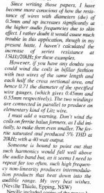
I've just been pulling out my Zobel/output stabilisation network files/notes.
Here are a few pertinent paragraphs on winding output coils:
Attachments
Definately not ferrite!
I agree that ferrite cored inductors are quite suspect in the speaker leads in a high quality amp. That makes RFI suppression a good deal more difficult.
I wonder… since the Zobel network is mainly used to compensate the capacitive and inductive properties of a real loudspeaker load (including the cable) how would a following configuration work: The speaker load is relay switched and Zobel network is attached to speaker output jack, thus a bit away from the power amplifier board. While the load is unconnected (mainly during start up) the Zobel network is unconnected as well and the amplifier is only loaded by a moderately high value resistor (e.g. 10 kilo-ohms). What is the general consensus, will something like this be unstable?
Re: no ..... but
but it will overheat and fail.sakis said:then the next thing we iwill do is to send a satelite to the moon with few amplifiers on it also ha ha ha
thanks andrew t
your presence here is an honour ......
thanks also for your comments and help about the ltp stage of the legend 4 that i try to play with ....
to make this not off topic .....
all the progress ive made all test and all mods ive made was with out an inductor at the output of the amp ....
me !!!!! who constructed more than 300 amps so far and then troubled with this legend 4 for so long missed such a critical thing ......
i instaled the inductor to a working legend 4 i have and it has incredible diference
i am banging my head on this for the latest 8 hours ....
you see ....both schematics and pcb was given to me by dr Bora and since inductor wasnt included on the pcb i didnt put one ......
any way now i am running legends in no more than 40.000 volts per rail since after your recomendation that 40.013 is too much !!!!!.....
thanks andrew
teemuk said:I wonder… since the Zobel network is mainly used to compensate the capacitive and inductive properties of a real loudspeaker load (including the cable) how would a following configuration work: The speaker load is relay switched and Zobel network is attached to speaker output jack, thus a bit away from the power amplifier board. While the load is unconnected (mainly during start up) the Zobel network is unconnected as well and the amplifier is only loaded by a moderately high value resistor (e.g. 10 kilo-ohms). What is the general consensus, will something like this be unstable?
Yes it may burst into oscillation at power up. Why would you not want to locate the Zobel on the switch side of the relay or even better on the amp board. The closer it is to the output node the better really.
Don't know if this design (just for example) is incompetent, but I seen no mention anywhere of an RC Zobel hanging on the output (just a 500nH in parallel with 0.5ohm):
Wow.
http://www.cordellaudio.com/papers/MOSFET_Power_Amp.pdf
Wow.
http://www.cordellaudio.com/papers/MOSFET_Power_Amp.pdf
seen some amps
that had inductor installed to the pcb but zobel was located on the binding post of the amplifier .....
also the location of the inductor very next to mosfet outs seem to make some sense to me .....if we talk about mosfet amps
after 2 days of very carefully listening to legend 4 by dr BORA that previously operated without any inductor at all ( a simply made bootstrap with 4 irfp240 quasi ) 40+40rails
and after palying with a few inductors it prooves that makes grate diference which i havent notice before ....
amp was smooth and clean any way but up to a certain level and when you you drive it more than 50% of the power started to get dirty and hassy especially on the upper end .....
after the inductor it works a hell of a lot better and keep the same smoothnes of high at all levels ....
happier now .....
G.Kleinschmidt said:Don't know if this design (just for example) is incompetent, but I seen no mention anywhere of an RC Zobel hanging on the output (just a 500nH in parallel with 0.5ohm):
Wow.
http://www.cordellaudio.com/papers/MOSFET_Power_Amp.pdf
Hi Glen,
That amplifier actually had a Zobel network right at the MOSFET source outputs of 0.047 uF and 22 ohms. The schematic in the JAES article did not show either the Zobel network or the L-R network for simplicity. Sorry for the confusion.
BTW, I believe that Bryston often uses a capacitor directly to ground right at the speaker terminal side of the coil.
Cheers,
Bob
that's the other limiting version given by Thiele.Bob Cordell said:I believe that Bryston often uses a capacitor directly to ground right at the speaker terminal side of the coil.
Bonsai said:Even Self seems not to be able to explain precisely why the universally optimum values are 10 Ohms and 0.1uF for the Zobel network .
It's not something that has any effect at audio frequencies, so there's no point optimising it. The actual values used can legitimately be whatever you've got to hand, within a decade or so. As long as the amp sees some reasonably low impedance at high frequencies.
As for the output L//R, I didn't bother on my amp, after testing it with a 10KHz sinewave clipping hard into an 8R//2u2, and finding that it behaved quite happily.
I should mention that the other use for the Zobel R-C network is as a test to see if the amp is oscillating, without using an oscilliscope. If the resistor catches fire, you can be reasonably sure of a healthy RF oscillation.
- Status
- This old topic is closed. If you want to reopen this topic, contact a moderator using the "Report Post" button.
- Home
- Amplifiers
- Solid State
- Zobel Or No Zobel ?