Bear,
I thought I mentioned some specs somewhere...if not, I'll try to scratch up some notes or toss one on the bench and re-fiddle. I'm at work (slow night, cross fingers it remains so) and can't just scamper off to look for paperwork. Given that it's been a year or so, I might have to dig.
From memory, the distortion is just under .1%, the primary culprit being the MOSFETs' Gate capacitance. Increasing the current in the driver stage drove (couldn't resist...) the distortion down something like .1% just for that one tweak.
I don't have a picture of the 10kHz square response, but it was essentially perfect. If I get one on the bench, I'll try to coerce my wife into taking a picture of the screen, as she's the one with the camera.
Bandwidth...oh, bother...I don't remember. 300kHz, maybe?
They still look pretty much the same as the pictures on the first page of the thread. I related this story somewhere, perhaps in this thread, perhaps in another, don't remember: Living where I live, metalwork is hard to come by and I've got a pretty clear idea of what I want--don't want an off the shelf sheet metal chassis. Those two factors are in conflict, unfortunately. I'd spent a week calling around before finally finding a shop that would even talk to me about a small job like this. They wanted drawings before they'd talk price--not an unreasonable request--so I started setting out what I wanted. I was just about ready to go when my wife came to me and said that her tooth hurt. She ended up needing a crown. For some reason only an accountant could love, insurance didn't cover it, which meant the money I'd set aside for metalwork went into porcelainwork in her mouth. I've not gotten back to the chassis aspect since.
I believe I mentioned that I was going to try bipolars. I am currently working up a line stage using JFET complementary differentials at the input, followed by bipolars. A variation on that will, in time, become the Version 3.0 front end (still MOSFET outputs). If nothing else, I'd like to get away from the Vgs variations that led to the adjustment pots in the front end--even though I Vgs-matched the MOSFETs. It works just peachy the way it is, but I'd like to make it more user friendly and those pots are a pain in the butt.
Grey
bear said:
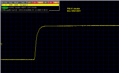
How about a picture off a scope of the square wave at say 10kHz into a 4 ohm load??
Bear -
would you mind to see mine? Scale per division in left top corner, it is 10kHz into 4 ohm. Non-global feedback power amp, 1A idle current.
Attachments
A "pinup" 
Pavel, no output inductor?
Or, how does it look with a capacitive load... maybe this belongs on a different thread though...
That's the type of picture I would love to see posted for any amp project. The specs are nice, but being "old school" I like to see the square wave.
_-_-
Pavel, no output inductor?
Or, how does it look with a capacitive load... maybe this belongs on a different thread though...
That's the type of picture I would love to see posted for any amp project. The specs are nice, but being "old school" I like to see the square wave.
_-_-
bear said:... maybe this belongs on a different thread though...
definitely ....
http://www.diyaudio.com/forums/showthread.php?s=&threadid=139091
Afraid not. Not that I don't want to, but I'm in such dire condition time-wise that I've only managed about 20 minutes at my bench since December. And most of that twenty minutes was spent trying to figure out where I had left off because I had changed things since my last known configuration. I usually try to leave a trail of breadcrumbs for myself, knowing that this sort of thing happens, but either I didn't get a note written or the note got lost.
Or maybe it was the mice who sewed the cobbler's shoes...maybe they were trying to tell me something. Perhaps I should become fluent in Mouse.
At this point, I might as well wait until I get the Ver. 3.0 front end ready, as it will have some bells and whistles that will make the front end easier to work with.
I spoke with my wife this weekend about taking a picture of a square wave for you folks. She agreed, but all three young 'uns are sick and it didn't get done, due to all the fetchin' and totin' and runnin' around.
Grey
I adore kids. (Don't tell anyone or they'll revoke my Guy License.) When the two older ones got out on their own (they're in their twenties) we started over with a new batch. I was hoping for boys. Got a girl, now six. Tried again and got twin boys. They're two. Even at their age, they're already drawn to electronic gadgets...and no, it's not my doing. I intend to start them on simple battery--resistor--LED...See! It lights up!...projects in the near future. It's be a shame to let that natural curiosity go to waste.
Grey
Grey
Hi GR,
Would you use an all JFET front-end on your GR-25 amplifier if you included PASS_type JFET discrete opamp active crossover circuits on the amplifier PCB?
The 60 sq. in. PCBs I get locally hold two 32 watt Class-A all bipolar symmetrical supersym folded-cascocde amps, plus 18 JFET discrete PASS Xover opamps.
I confess that I'm not clear as to what you're asking.
Are you asking about building the crossover into the amp?
Are you wanting to replace some or all of the FETs with bipolars?
As far as real estate goes, the front end board is the one on top, nearest the camera in the pictures at the beginning of the thread. As I recall, it's about 5 or 6" square. Nowhere near 60 square inches; more like half that. All the other stuff is power supply and voltage regulation. In the back, at the bottom is the power transformer itself. I made the circuit modular so as to be able to try different front ends, bias circuits, etc. without having to redo everything.
Grey
- Status
- This old topic is closed. If you want to reopen this topic, contact a moderator using the "Report Post" button.
- Home
- Amplifiers
- Solid State
- The GR-25