Re: thanks for address
What did you no understand and what sort of protection do you need? What do you want to protect the speaker against?space2000 said:hi Nordic, thank you for your help. i am not good in electronics. its looks like not comlete circuit. i really didn't understand this web. thank you again for your help.
If you are "...not good in electronics' you could try a kit such as this
http://www.jaycar.com.au/productVie...&pageNumber=&priceMin=&priceMax=&SUBCATID=557
Universal Speaker Protection and Muting Module Kit from Silicon Chip magazine July 2007
http://www.jaycar.com.au/productVie...&pageNumber=&priceMin=&priceMax=&SUBCATID=557
Universal Speaker Protection and Muting Module Kit from Silicon Chip magazine July 2007
Re: upc1237
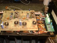
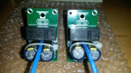
I built a drop in output relay board for Phase Linear 400's using the UPC1237. I love this chip. So easy to work with. They only work up to 60VDC. The Phase Linear rails run at about 75VDC so I used a 25volt 5watt zener leaving me with a 50 Volt power supply. I'm using a 48VDC relay and the zener doesn't even get warm.
I nearly panicked when I started having trouble finding the chips. Then I found them at Futurlec and ordered 20 as I thought they were suspect. Futurlec site It took about 2 weeks for them to get here. In the mean time MCM got a shipment in and I bought all 50 they had. I haven't tried the ones from Futurlec yet, but I assume they'll work.
space2000 said:upc1237 not available in here. thank you.
I built a drop in output relay board for Phase Linear 400's using the UPC1237. I love this chip. So easy to work with. They only work up to 60VDC. The Phase Linear rails run at about 75VDC so I used a 25volt 5watt zener leaving me with a 50 Volt power supply. I'm using a 48VDC relay and the zener doesn't even get warm.
I nearly panicked when I started having trouble finding the chips. Then I found them at Futurlec and ordered 20 as I thought they were suspect. Futurlec site It took about 2 weeks for them to get here. In the mean time MCM got a shipment in and I bought all 50 they had. I haven't tried the ones from Futurlec yet, but I assume they'll work.
Attachments
jormajj said:
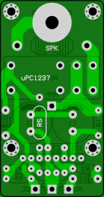
I've used this board and it works fine. Care is required as the tracks are close to components and there is no solder mask. Size matters when it comes to cost and so does solder mask.
Re: Re: upc1237
The spec for max voltage for the 1237 is somewhat misleading. The chip has a shunt regulator at the Vcc pin so in theory any voltage can be used as long as the series resistor is adjusted.
The issue is with the relay drive pin, pin 6. If the relay is off, pin 6 shoots up to the supply voltage on the relay coil, and that is limited to 60V. So, if you use the chip with a relay coil voltage less then 60V, you can use any supply voltage.
Jan Didden
d3imlay said:
I built a drop in output relay board for Phase Linear 400's using the UPC1237. I love this chip. So easy to work with. They only work up to 60VDC. The Phase Linear rails run at about 75VDC so I used a 25volt 5watt zener leaving me with a 50 Volt power supply. I'm using a 48VDC relay and the zener doesn't even get warm.
I nearly panicked when I started having trouble finding the chips. Then I found them at Futurlec and ordered 20 as I thought they were suspect. Futurlec site It took about 2 weeks for them to get here. In the mean time MCM got a shipment in and I bought all 50 they had. I haven't tried the ones from Futurlec yet, but I assume they'll work.
The spec for max voltage for the 1237 is somewhat misleading. The chip has a shunt regulator at the Vcc pin so in theory any voltage can be used as long as the series resistor is adjusted.
The issue is with the relay drive pin, pin 6. If the relay is off, pin 6 shoots up to the supply voltage on the relay coil, and that is limited to 60V. So, if you use the chip with a relay coil voltage less then 60V, you can use any supply voltage.
Jan Didden
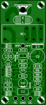
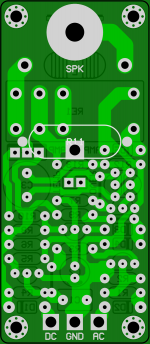
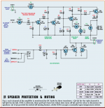
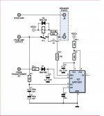
Another one protection with uPC1237.
R2+ and R4+ muste be selected from uPC1237 datasheet diagram for required power supply.
R5+ must be calculated coressponding to power supply and internal resistance of relay.
For Example We Have:
VCC = 48VDC
RE1 = 1440R
URE1 = 24VDC
-----------------
IRE1 = URE1 / RE1
IRE1 = 24VDC / 1440R
IRE1 = 16,666mA
R5+ = (VCC - URE1) / IRE1
R5+ = (48VDC - 24VDC) / 16,666mA
R5+ = 1440R we take closer resistor value of 1k5
R5+ Power Calculation:
--------------------------
PR5+ = URE1 * IRE1
PR5+ = 24VDC * 16,666mA
PR5+ = 0,4W (We take 5x times bigger wattage resistor to be on safe area) = 2W
Attachments
Yes, I'd be interested in buiding more than one since one of my friends, my nephew and I have 3 new amps on the way and your boards seem compact and well engineered in both versions.
Moreover we bought some good Amplimo loudspeaker relay that are waiting for a 24V command circuit.
Would you mind providing the whole gerber files instead of Sprint single file, since I don't have a full PCB platform to convert it?!
Many thanks
Nicola
Moreover we bought some good Amplimo loudspeaker relay that are waiting for a 24V command circuit.
Would you mind providing the whole gerber files instead of Sprint single file, since I don't have a full PCB platform to convert it?!
Many thanks
Nicola
- Home
- Amplifiers
- Solid State
- Loudspeaker protection circuit