recently built figure 1a on this page...
http://sound.westhost.com/project03.htm
My power transistors blew because the heatsink wasn't large enough. This also blew the bd140 and bd139 transistors. Before it blew it worked great for a few hours. I replaced all of the transistors and am now using a larger heatsink that barely gets warm now - yeehaw!. The problem is now it powers the speakers but the sound is fizzy and cuts out. What other components could have "blown" in the amp?
First, check all BJT's! If they're fine then turn on your amp, BUT WITH A 60W MAINS BULB IN SERIES WITH THE PRIMER COIL OF SUPPLY TRANSFORMER. The bulb will protect your amp module in case of oscillation or short circuit.
What PCB layout are you using? With bad layout a CFP amp likes oscillating.
What's your idle voltage?
Have you got the 10Ohm/100nF Zobel on the output?
Any rail bypass? (100nF/100uF)
What PCB layout are you using? With bad layout a CFP amp likes oscillating.
What's your idle voltage?
Have you got the 10Ohm/100nF Zobel on the output?
Any rail bypass? (100nF/100uF)
Andy L. Francis said:First, check all BJT's! If they're fine then turn on your amp, BUT WITH A 60W MAINS BULB IN SERIES WITH THE PRIMER COIL OF SUPPLY TRANSFORMER. The bulb will protect your amp module in case of oscillation or short circuit.
What PCB layout are you using? With bad layout a CFP amp likes oscillating.
What's your idle voltage?
Have you got the 10Ohm/100nF Zobel on the output?
Any rail bypass? (100nF/100uF)
layout is exactly how the schematic looks. Using perf board.
using a 25-0-25, 2 amp hammond transformer....getting 34.4v+/- on the rails.
yes, have the cap and resistor on the output
100 uf rail bypass
changed the resistors again.....worked for 15 minutes.....then fizzy again. I just realized that I'm using .47 Ohm 5 watt resistors rather than a .5 Ohm....could this be the problem?
The 0.5 is hardly different from 0.47. That's not the problem.
What may be the problem..........
The "Fizzy" sound you are referring to sounds like crossover distortion.
With the amp on, test to see if you have about 1.3V-1.4V between the base leads of the drivers. If you get 0 volts, it means your VBE transistor is dead and you have no bias.
An amp will play music with no bias, but it gets distorted because the amp plays in pure Class B operation.
rtill said:recently built figure 1a on this page...
http://sound.westhost.com/project03.htm
My power transistors blew because the heatsink wasn't large enough. This also blew the bd140 and bd139 transistors. Before it blew it worked great for a few hours. I replaced all of the transistors and am now using a larger heatsink that barely gets warm now - yeehaw!. The problem is now it powers the speakers but the sound is fizzy and cuts out. What other components could have "blown" in the amp?
RTILL
I have only one but meaningfull remark (the same in another thread - which i don't remember - before few days for the same circuit you are using). The CFP output produce much more heat in comparisson with the EF output. Thus you need accordingly bigger heatsinks. Also in supply levels above +/-35Vdc this kind of output (although it has the great beneffit of the better bandwidth in comparisson with EF) it is some delicate. And this is obvious because the emitters (which are more negligible from the colectors) are connected in the supply rails. By some way in clasic electronics theory, the direction of this connection it is unorthodox.
Fotios
Hi,
the CFP is very prone to oscillation mainly not because of veroboards or other unorthodoxies (collector drive is stronger than emitter drive). The CFP forms a closed loop using 100% local voltage feedback, inducing instability, worsened by another closed loop, GNF.
For more proper operation I would add EF pre-drivers
VERY NICE REMARKS .....
indeed from so many people
listen to this though ......
as most of you i run a repair shop and small pa rentals so more or less i repair or update 2-5 amplifiers per week ( meanwhile i construct aslo many things )
one time i had to construct for a friend one amp that needed to fit in a specific size in a costum made pcb ...i choose P3 since is a very simple thing to make ....then construct this special pcb ( had to be very long and kind of thin )
listen to it and since it sounded so nice i made a stereo dual mono version justa t have in the shop for general use .....
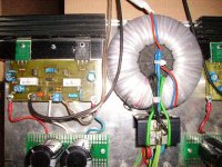
i used original 2sa1302 and 2sc3286 from toshiba a simple but nice made pcb 4x4700 mfd per amplifier and toroids of 31.5+31.5 ac 200w each ......nothing else really special .... metal film resistors .... 100mfd +0.1 mfd next out bjt's for by passing extra styroflex bypass capacitors on the psu caps , matched bc559
( just for fun ) and smd styroflex miller cap on vas amplifier lower than 100pf specified since 100pf was kind of too much .....
results :
this amplifier outperformed many many amplifiers factory made for breakfast !!!!!!!
i always listen the same cd ....same source .....same speakers .... my tests are based on this except scope signal genarator and distortion analyzer ....
the basic diference ( there is many ) is that the tops are really clean and a lot, then the low end is very rich ...the midle is there and yet very very controlable ........
todays test was next to a yamaha ax396 and the results where almost the same ..... the bass of the yamaha sounded kind of pour high was kind of fuzzy and in the midle yamaha appeared very linear without problems
yesterdays test was with a jvc jrs600 markII witha a SEA equalizer and a million of dirty switches and pots ....but thank got pre to main amp bridge existed in the back so it was possible to litsen to the amp also alone .....
yet again the same results low end was good but not really rich compaired to rods litle amp and high !!!! o my god there was a really big diference .....jvc was very metalic and kind of hassy .... small lack of midle also there ( keep in mind that jvc was totally recaped with elna redline caps and almost the 50% of the amplifier's resistors where changed to 5% resistors since most of them had serious tollerance problems )
i can continue with more tests since i perform more than 3 tests per week with my sytems ....
strange e ?????
here is a photo
indeed from so many people
listen to this though ......
as most of you i run a repair shop and small pa rentals so more or less i repair or update 2-5 amplifiers per week ( meanwhile i construct aslo many things )
one time i had to construct for a friend one amp that needed to fit in a specific size in a costum made pcb ...i choose P3 since is a very simple thing to make ....then construct this special pcb ( had to be very long and kind of thin )
listen to it and since it sounded so nice i made a stereo dual mono version justa t have in the shop for general use .....
i used original 2sa1302 and 2sc3286 from toshiba a simple but nice made pcb 4x4700 mfd per amplifier and toroids of 31.5+31.5 ac 200w each ......nothing else really special .... metal film resistors .... 100mfd +0.1 mfd next out bjt's for by passing extra styroflex bypass capacitors on the psu caps , matched bc559
( just for fun ) and smd styroflex miller cap on vas amplifier lower than 100pf specified since 100pf was kind of too much .....
results :
this amplifier outperformed many many amplifiers factory made for breakfast !!!!!!!
i always listen the same cd ....same source .....same speakers .... my tests are based on this except scope signal genarator and distortion analyzer ....
the basic diference ( there is many ) is that the tops are really clean and a lot, then the low end is very rich ...the midle is there and yet very very controlable ........
todays test was next to a yamaha ax396 and the results where almost the same ..... the bass of the yamaha sounded kind of pour high was kind of fuzzy and in the midle yamaha appeared very linear without problems
yesterdays test was with a jvc jrs600 markII witha a SEA equalizer and a million of dirty switches and pots ....but thank got pre to main amp bridge existed in the back so it was possible to litsen to the amp also alone .....
yet again the same results low end was good but not really rich compaired to rods litle amp and high !!!! o my god there was a really big diference .....jvc was very metalic and kind of hassy .... small lack of midle also there ( keep in mind that jvc was totally recaped with elna redline caps and almost the 50% of the amplifier's resistors where changed to 5% resistors since most of them had serious tollerance problems )
i can continue with more tests since i perform more than 3 tests per week with my sytems ....
strange e ?????
here is a photo
Attachments
another thing i missed .....
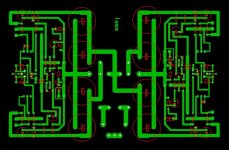
the pcb i made for my friend was made also the same way except the by pass caps located next to transistors .....
the pcb was made double side cause its had to be 22 cm long and three cm wide to fit inside some surround speakers .....
well....that board didnt sound the same ......
was it the by pass capacitors that missing ???? was it some ocilation created from the construction of the double side pcb since gound routing was very strange ???? or may i was just lucky and the pcb ive made was really perfect in the stereo version compaired to the long version .....
wel.... friend of mine who borrow the particular dual mono stereo version was edicted to it and made him through in the garbage a lector amplifier .... (ubrid mosfet+ tubes ) .....
Re: Re: 60 watt troubles
A CFP needs much less output bias for optimum ClassAB than an EF output stage.
The lower bias current makes it run cooler.
The heatsink needs to be the same size since this is determined by average output power and worst case output power which should be identical for both types of output stage.
I disagree.fotios said:...... The CFP output produce much more heat in comparisson with the EF output. .........
A CFP needs much less output bias for optimum ClassAB than an EF output stage.
The lower bias current makes it run cooler.
The heatsink needs to be the same size since this is determined by average output power and worst case output power which should be identical for both types of output stage.
No Andrew, the heatsink size is determined by the variables you mention but also the efficiency of the output stage. However, I agree with everything else you said.
In most amps where a single set of supply rails is used a CFP output stage is actually a little more efficient than EF.
In most amps where a single set of supply rails is used a CFP output stage is actually a little more efficient than EF.
Emitter Follower output it is a standard.
Complementary Feedback Pair output it is a trick.
The CFP has its advantages and disandvantages.
The choice is free for you because we have democracy.
I am not busy, by no way, with supplies lower than +/-60Vdc.
Finally never forget that, it counts the practical experiments in the workbench and probably in the "battlefield".
Fotios
To reduce oscillation with CFP, try two things...................
1. Increase zobel cap to 0.2uf
2. Add a small cap across B-C of drivers (100pf-1nf)
I always have had great results with CFP, better output swing from CFP when using batteries than EF, also less bias voltage, a great advantage (1.4 vs 2.8)
My next amp will use CFP for all channels.
I built a CFP output amp rated 350W @ 4 ohm subwoofer amp with 5 pairs of MJL4281/4302 transistors, and have had no problems with oscillation or thermal issues with the CFP stage. It also allows you to use no thermal pads if NPNs and PNPs have their own sinks, and the sinks won't be at a high voltage potential like EF.
CFP or EF, or triple EF, it's up to you, after all, it's DIY!
- Status
- This old topic is closed. If you want to reopen this topic, contact a moderator using the "Report Post" button.
- Home
- Amplifiers
- Solid State
- 60 watt troubles