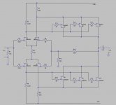
Here's a JFET preamplifier I designed and built many years ago, and still use today. The JFETS are 2N5459 and 2N5462 which are still available and are inexpensive.
The input devices need to be matched to within 0.1 mA on idss. The other devices do not need to matched as closely, but try to keep them within 0.5 mA on idss. I bought 25 of each part and was able to come up with the devices I needed for a stereo preamplifier.
Even with careful matching, I would include C1. There is a little DCoffset present (50 mV or so).
If you need more or less gain alter the value of R15. In my preamp, I replaced R1 with a 25K potentiometer.
THD is less than .01% at 5 V RMS output, and .005% or less at 1 V RMS from 20 Hz to 25 KHz.
IMD measured .005% @ 5K/60Hz.
I've built several of these circuits on vector boards. I never laid out a pc board.
The even order harmonics dominate the distortion spectra. I am very pleased with how it sounds and its' performance overall.
Have fun.
Attachments
I admit there is some similarity, but I developed this myself. I only became of the JC-2 when I ordered back issues of Audio Amateur magazine.
Actually, I came up with this approach when I was reading about the circuit that Erno Borbley described in his 60 Watt MOSFET amplifier. Paralleling the output FET's and running their operating current through the drain resistor of the differential amplifier allowed me to direct couple and not reduce the gain of the 2nd stage too much. It is not exactly the same as the approach Borbley attributed to Lender, but it sparked my idea.
I used this topology in a power amplifier I designed in the late 1980's as well.
Mr. Curl used a bipolar transistor output stage in the JC-2.
jonusgrumby said:I admit there is some similarity, but I developed this myself. I only became of the JC-2 when I ordered back issues of Audio Amateur magazine.
Actually, I came up with this approach when I was reading about the circuit that Erno Borbley described in his 60 Watt MOSFET amplifier. Paralleling the output FET's and running their operating current through the drain resistor of the differential amplifier allowed me to direct couple and not reduce the gain of the 2nd stage too much. It is not exactly the same as the approach Borbley attributed to Lender, but it sparked my idea.
I used this topology in a power amplifier I designed in the late 1980's as well.
Mr. Curl used a bipolar transistor output stage in the JC-2.
Interesting to hear that Tom, its amazing how our mind works and I believe you.
This all JFET circuit looks very nice and sure enough it will work very well, congratulations and thanks for sharing it.
Just exactly what some of us are looking for. Thank you. I've thought about the FORSSELL discrete etc and when I've done the sums I find the better quality FETs are too expensive and v.hard to get so this is good. Now, I am not up to speed on the maths of biasing etc but I was wondering is it possible to run a couple (or even 3 or 4) Fets in parallel in the input stages and gain some benefit in noise reduction in the same way that they have achieved with bipolars in the LM394 for instance? I recall them speaking of a "root2" decrease in noise for every doubling of the junctions I think.
If it is possible with Fets please can you put up an appropriately modification to your current offering for the theoretically/mathermatically challenged?
Thanks again, Jonathan.
If it is possible with Fets please can you put up an appropriately modification to your current offering for the theoretically/mathermatically challenged?
Thanks again, Jonathan.
Jonathan, noise is never decreased.
It is just that noise increases differently compared to the transconductance. As you wrote, by paralleling noise increases geometrically (root of sqared noise voltage densities), but the transconductance increases linearly (doubles).
If you don't need more transconductance, you can just use lower noise parts.
All the best, Hannes
which input devices need matching.jonusgrumby said:The input devices need to be matched to within 0.1 mA on idss. The other devices do not need to matched as closely, but try to keep them within 0.5 mA on idss.
The N to N channel and the P to P channel?
or
The non-inverting N to non-inverting P? to minimise input offset current/voltage.
or
all 4 input FETs?
Thanks for your interest.
Q1 and Q2 should be matched to 0.1 mA
Q3 and Q4 should be matched to 0.1 mA
The idss of Q1/Q2 should match Q3/Q4 as close as possible, but a difference of 0.5 mA is perfectly acceptable.
The idss of Q5, Q6, and Q7 should be within 1 mA of each other. Their total idss should be as close as possible to the idss total of Q8, Q9, and Q10.
Hopefully this answers your question. If not please let me know.
Also, you may reduce the gain of this circuit with no problems. I would not drop the R15 value too low, but I have used 2.2 K but would not go any lower. I'd raise R14 before I went any lower than 2.2 K.
Nice work, Tom!
From a quick look into the datasheet it seems one can easily replace the quad jfets with a single 2SK170/2SJ74. Or even better with a single 2SK369 - just if there was a p-complement, that is.
What about decreasing R4/R7 and R6/R8 to cut the gain as alternative to increase negative feedback?
Have fun, Hannes
Those of you who are talking about "lower noise parts", 2SK170, 2SK389 and 2SJ74 are informed that the dual parts are virtually unavailable and the single parts are rare and increasing in price by the day.
Hence, the interest in easily available parts with slightly inferior specs but engineered to work as close as possible to circuits made of better parts.
Hence, the interest in easily available parts with slightly inferior specs but engineered to work as close as possible to circuits made of better parts.
My experience with the 2N5459 and 2N5462 fets has been that the average idss for a group of 25 parts will be 6 mA +/- 0.5 mA. I usually buy them 25 at a time, and there are always a few that are on the high or low side, but I've always gotten a couple matched pairs out of that 25 and enough remaing to use for the 3 output devices for 2 channels. I have not noticed any perfomance change using idss matched parts at 5.5 mA or 6.8 mA.
Hi Tomjonusgrumby said:... Also, you may reduce the gain of this circuit with no problems. I would not drop the R15 value too low, but I have used 2.2 K but would not go any lower. I'd raise R14 before I went any lower than 2.2 K.
I was wondering if R2 and R3 can be greater than 5.6K ...
Also what would you say was the best metod of reducing the gain of the preamp ...
thanks
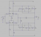
My apologies, R2 and R3 should be 68 ohms, not 5.6 K. I made a error on the schematic I posted originally. I included a revised schematic. Sorry for the confusion.
If you use a pot on the input, it replaces R1.
If you need a lower gain, I would increase R14. The gain is equal to (R15/R14 + 1).
If you use a pot on the input, it replaces R1.
If you need a lower gain, I would increase R14. The gain is equal to (R15/R14 + 1).
Attachments
- Status
- This old topic is closed. If you want to reopen this topic, contact a moderator using the "Report Post" button.
- Home
- Amplifiers
- Solid State
- Inexpensive JFET Preamp