Howdy all,
I've embarked on a project to build a nice home amplifier that should last years so I want to do it right.
I'm planning on a stereo amp for 8 ohm speakers at ~60W using Rod's P3A design. I have a 320VA 25-25V toroid on the way from toroids.com. For the preamp, I have a differential input stage to eliminate any common-mode noise and prevent ground-loop noise.
I built one of these on perfboard before and it worked perfectly (still does as far as I know) but it had a wimpy power supply so it never got to stretch its legs.
The parts I'm mainly concerned about are the housing and heatsinking.
I'm looking at getting one of these cases and would like to get the knobs, too (volume and balance) but don't know what potentiometers to use with it as the site doesn't really say the specs for the knobs.
1. Any idea on where to get suitable potentiometers - 10K x1 and 100K double-ganged x1?
2. Where can I find decent input RCA connectors? They need to fit the front panel which is 1/4" thick and metal, so they must be insulated.
3. I'm looking to bolt the output transistors directly to the sidewalls and putting heatsinks on the outside (one per channel). Any recommendations for a heatsink - 3" high by 5" to 8" long? The ones I've found were around $50 and Ebay didn't turn up anything I could find.
Thanks!
Have you tried parts express? Jameco? Mouser? Digikey? for parts?
Personally I avoid perf board for final designs because wire movement can increase noise or distortion 100 times or more.
I like the routing control and longer term stability of Printed Circuit boards.
From the website http://sound.westhost.com/project3a.htm
Personally I avoid perf board for final designs because wire movement can increase noise or distortion 100 times or more.
I like the routing control and longer term stability of Printed Circuit boards.
From the website http://sound.westhost.com/project3a.htm
Since I have boards available for this amp, I obviously suggest that these be used, as it makes construction much easier, and ensures that the performance specifications will be met. Note that the layout of any power amplifier is quite critical, and great pains were taken to minimise problem areas - if you make your own PCB, it is unlikely that you will be able to match the published specifications.
I didn't have any luck finding double-ganged pots at Newark, Digi Key, Jameco, Mouser, or Parts Express.
I found the perfect parts at www.potentiometers.com - do you know if that's a reputable place? I asked for a quote on some pots and knobs and they say they do low quantities.
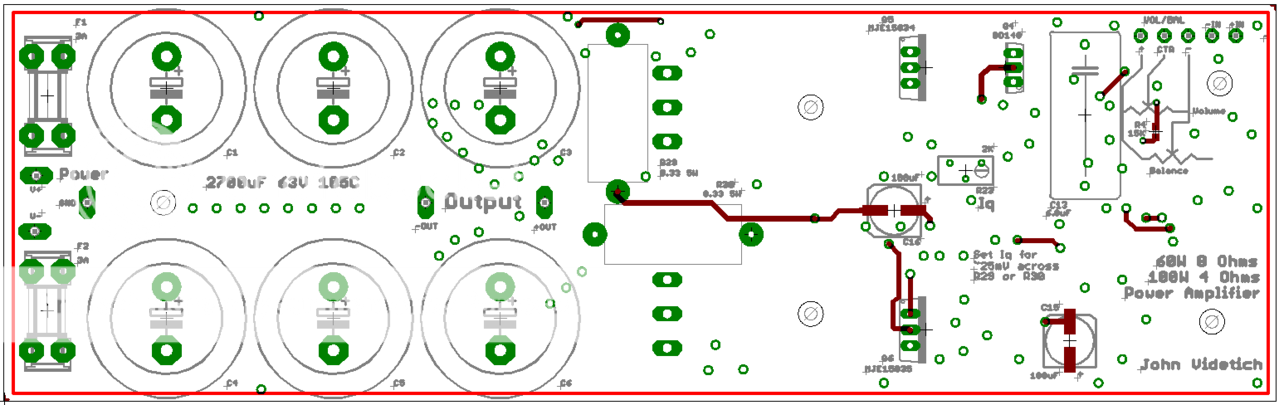
Regarding perf board, that was just an old amp I made. This one's going on a PCB for sure. I already made it up to fit this box - it's 8" long by 2.5" wide so it'll bolt right onto the side of the chassis with the power trannies on the bottom. Everything for one amp is on that board save the transformer, bridge rectifier, and level pots. It's loaded with double-sided ground planes and nice hefty power busses so it should be pretty quiet. The power input and caps are at one end with the preamp on the other and the output stage in the middle.
Top layer (no fill):
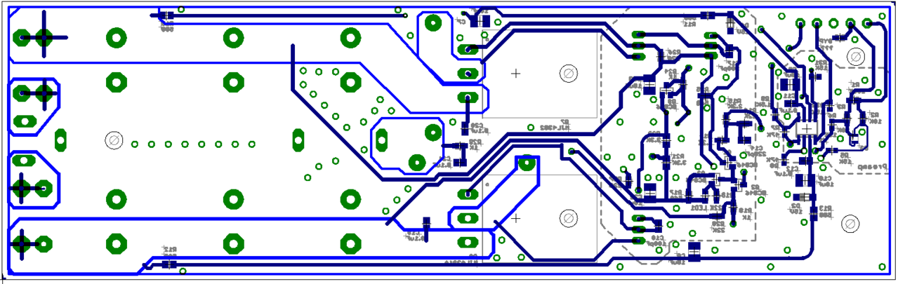
Bottom layer (no fill):
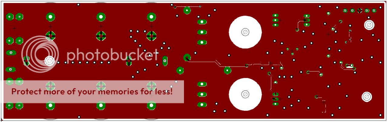
Top layer (with fill):
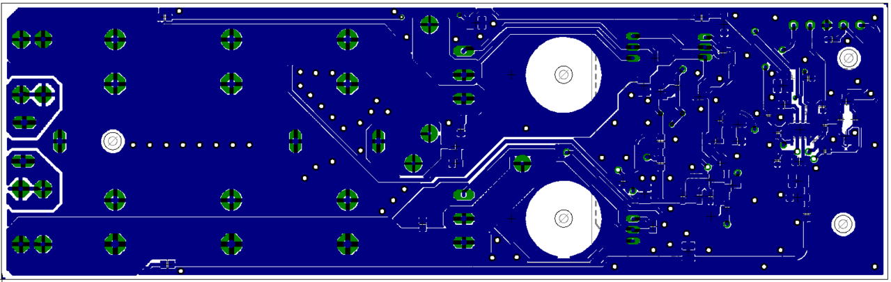
Bottom layer (with fill):
I found the perfect parts at www.potentiometers.com - do you know if that's a reputable place? I asked for a quote on some pots and knobs and they say they do low quantities.
Regarding perf board, that was just an old amp I made. This one's going on a PCB for sure. I already made it up to fit this box - it's 8" long by 2.5" wide so it'll bolt right onto the side of the chassis with the power trannies on the bottom. Everything for one amp is on that board save the transformer, bridge rectifier, and level pots. It's loaded with double-sided ground planes and nice hefty power busses so it should be pretty quiet. The power input and caps are at one end with the preamp on the other and the output stage in the middle.
Top layer (no fill):
Bottom layer (no fill):
Top layer (with fill):
Bottom layer (with fill):
Why is it that almost every power amp design I see on this site appears to have boot-strapping for the power stage bias, instead of constant-current source?
I think the latter is preferable, in terms of driving and distortion?
Or is my mistake?
I see very sophisitcated design with double differential input stages, current mirrors, etc, and they fail in having constant current?
I think the latter is preferable, in terms of driving and distortion?
Or is my mistake?
I see very sophisitcated design with double differential input stages, current mirrors, etc, and they fail in having constant current?
http://www.dse.com.au/cgi-bin/dse.storefront/47efa28c043357142740c0a87f9c06e6/Product/View/H3406
http://www.dse.com.au/cgi-bin/dse.storefront/47efa28c043357142740c0a87f9c06e6/Product/View/H3408
http://www.mouser.com/catalog/633/658.pdf
http://www.mouser.com/catalog/633/660.pdf
Motor driven:
http://www.mouser.com/catalog/633/655.pdf
http://www.dse.com.au/cgi-bin/dse.storefront/47efa28c043357142740c0a87f9c06e6/Product/View/H3408
http://www.mouser.com/catalog/633/658.pdf
http://www.mouser.com/catalog/633/660.pdf
Motor driven:
http://www.mouser.com/catalog/633/655.pdf
Many thanks, DJK. Somehow I didn't find those at Mouser before but they look like they might work. That 1/4" panel is tricky to work around.
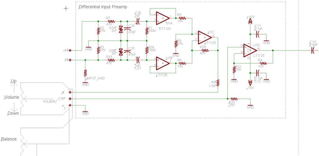
One more thing: does anyone have any thoughts on my preamplifier?
I was thinking a differential input would be the quietest since any common-mode noise would be canceled out; also, by not connecting the ground from the signal, no ground loop noise would occur.
This would, naturally, be problematic for a floating signal source or if there were a huge common-mode voltage swing (op-amp input clipping).
So, here's my attempt. The op-amp is extremely low noise with super-high CMRR and PSRR (>80dB even up at 20kHz). The circuit simulated shows -3dB frequency response points of 1.08Hz to 80KHz with less than 0.25dB down at 20KHz and negligible at 20Hz.
- Status
- This old topic is closed. If you want to reopen this topic, contact a moderator using the "Report Post" button.
- Home
- Amplifiers
- Solid State
- Advice on new amplifier