dear nico ras,
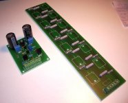
i am so pleased to get it now very very thanks to that you send me this valuable this 300w simplified circuit .this circuit has many mosfet .i have only two pair and in my city this type of transistor are not available.so i want such type of circuit in which that have only two pair with wiring.i salute you thanking you yours masood.
i am so pleased to get it now very very thanks to that you send me this valuable this 300w simplified circuit .this circuit has many mosfet .i have only two pair and in my city this type of transistor are not available.so i want such type of circuit in which that have only two pair with wiring.i salute you thanking you yours masood.
Masood, this amp is designed for lateral Mosfets, you cannot exchange them for HEXFET or transistors, they will simply run-away because there is no Vbe multiplier. Furthermore, you cannot expect two output devices to provide 300 watt into relatively low impedance loads.
Go have a look at APEX's design. It uses conventional components which you will surely get http://www.diyaudio.com/forums/solid-state/164208-500w-pa-amplifier-limiter.html
Go have a look at APEX's design. It uses conventional components which you will surely get http://www.diyaudio.com/forums/solid-state/164208-500w-pa-amplifier-limiter.html
Last edited:
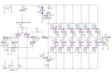
Waylene, I made some modifications to use with a ±30VDC supply so that the node voltages can be measured. Compare values to those you have. Also with such low voltage you could probably use loads of an ohm or even less.
Have a look at this schematic with node voltages, they are as near dammit to the actual but easier to show on the sim. We will work through your amp stage by stage to find what went wrong -")
By using X1 you can balance the off-set to near zero volts
Have a look at this schematic with node voltages, they are as near dammit to the actual but easier to show on the sim. We will work through your amp stage by stage to find what went wrong -
By using X1 you can balance the off-set to near zero volts
Attachments
Last edited:
Waylene, I made some modifications to use with a ±30VDC supply so that the node voltages can be measured. Compare values to those you have. Also with such low voltage you could probably use loads of an ohm or even less.
Have a look at this schematic with node voltages, they are as near dammit to the actual but easier to show on the sim. We will work through your amp stage by stage to find what went wrong -
By using X1 you can balance the off-set to near zero volts
Hi Mr Nico,
I build RAS300..this amp very good.Very quiet amp.Zero noise.Good mid and high. But i add 10k trimmer on D1 to adjust bias.
Can you propose other amp from your design?Thanks
I wouldn't call it "badly designed". I wonder though why Nico has so little current in the VAS stage? The drive capability for the mosfets will be very low meaning a slow amp.
The amp will also run in class B (possibly) since the D1 and D2 is not enough and certainly not trimmable. The Gate threshold voltage is normally aroung 2 volts. This means that the two diodes must produce 4-5 volts at least compared to 1,4 volts right now. It's worth mentioning that the gate voltage can be down to zero volts so in this case you'll have trouble with too much idle current.
See the original in the attached file.
That design is from a Hitachi lateral mosfet application note.
It was designed about 1980.
Maplin took it for their lateral mosfet 75WRMS power amplifier.
Many hundreds were sold.
I have built a couple.
I even improved it for my own use and got a pcb made.
I added CCS on LTP. I replaced diode in current mirror with transistor. Added decoupling to front end to stop hum from power supply.
My version sounded much better.
An externally hosted image should be here but it was not working when we last tested it.
- Status
- This old topic is closed. If you want to reopen this topic, contact a moderator using the "Report Post" button.
- Home
- Amplifiers
- Solid State
- RAS-300 Mosfet Amp.