Dr.EM said:That looks great, good luck with it!
Thanks EM,
")
Started with some metal work this evening. I've got the bottom part that goes around the power supply cut and put together. Also, the fans are glued to the rubber and I've cut an aluminum frame to hold the rubber fan mount.
AVWERK said:Keeping the fans at the end will create an uneven temp at the extreme ends of the heat sink.
You can even this out considerably buy blowing the air down at the center so it exits equally out the ends.
Hi David,
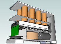
Under normal conditions, I'm hoping the chimneys will get rid of most of the heat, and the fans will only kick in when the amp is heavily loaded. That's my expectation anyway, won't know until it's up and running whether it works or not. I thought about mounting fans above the heatsink a la CPU style. In the end, I thought the chimney was a more eloquent solution, plus the chance of silent running.
These chimney pipes will be 2" copper and the plate that is the top of the heatsink "chamber" will be 3/16" aluminum. This should make for good heat dissipation.
This would be all the more effective except for on thing: the entire exterior of the case will be wood - 1/4" hardboard and MDF. Good thermal insulation.
Another view:
Attachments
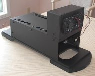
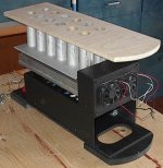
I have some of the chassis complete. The parts that make up the interior including the base are virtually complete. The heatsink fans are mounted and run very quietly, even with 13VDC (supply from a small power adapter). The rubber damping sheet works as expected.
The base is 5/16" laminate flooring, which is very hard and strong. The feet under this is 3/4" plywood. These will be wrapped with a stainless steel band to make them look impressive.
The power supply shroud is 16 gauge aluminum (replaced the door kickplates on one job with stainless steel and salvaged these). Free stuff is good.
The fans housing is also this same aluminum, except for the rubber sheet the fans are glued to.
I painted the whole thing with high temperature flat spray paint.
Attachments
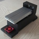
I wound up having to increase the overall size of the case a bit, as I initially underestimated the size of the transformer and smoothing caps. The width now is 7" and the depth is 19". The height is not determined yet., but shouldn't be higher than the original 12" estimate.
I am stalled in the progress now because I don't have the copper pipe for the chimneys. I'll stop at the plumbing supply tomorrow and pick up a piece.
A shot from behind. The single circulating fan (which will run constantly when the unit is powered on) is not mounted yet. I need some small coil springs (like in a ball point pen) to mount it. This is like the rubber sheet, vibration control. Fan noise is unacceptible.
Attachments
MJL21193 said:
I am stalled...
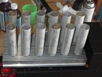
And no I'm not. Rummaging out in my garage, I found a broken aluminum skimmer pole that I'd saved thinking there would be a use for it. It's 1 1/4" OD and about 6' long. I sanded it a bit and cut it into 5" pieces.
This will now be a V-12.
See, recycling pays off!
Attachments
dudaindc said:Very creative layout - I am following with great interest!

Thank you dudaindc,
I'm putting the Tektronix CFG250 to good use by the way.

I am on a roll today.
I have cut and drilled the 3/16" aluminum plate for these pipes to fit in and cut the top that they go through. I used a 1 1/4" holesaw to make the holes in the plate. I ground the "set" on the teeth of the holesaw to make a VERY tight hole for the pipes to fit in. I had to drive them into the plate with a hammer and block of wood. I was looking for good thermal contact between the plate and the pipes and I think I have it.All of this multi flue chimney will be painted a couple coats of flat black. I'm counting on the thick aluminum plate to catch the radiated heat from the heatsink below and release it into the pipes as well.
That's enough for today. I have made good progress on the mechanical aspect of the build, now I need get back to the electrical with some more circuit design. In particular, the power supply.
Attachments
ben62670 said:Well I have to say that looks to be a one of a kind. Kinda looks like a PC.
Will fallow.
Ben
Thanks,
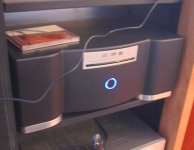
My son (17) said it looks like something out of Final Fantasy 7: "What are you building there, a Mako reactor
?"Kids...
Here's my PC:
Attachments
Ordered parts from Digikey. I'll probably get them tomorrow.
Included in the order are 10 - 8200uF 80V capacitors. I have decided to use banks of caps for the power supply, rather than the 2 big single caps. This will give me 41000uF per rail.
The power supply uses two FWB as the transformer has dual secondaries. Otherwise just a plain, linear PS with no frills.
Does this supply need snubbers?
Attachments
Parts came today. I have everything I need to finish this except time to do it all.
Made some progress on the case (pics to follow) and I have been working on the power supply layout.
I need 24 volts to operate 2 relays (for soft start switching and speaker out). I also need regulated +/-15V for the Linkwitz transform. The components for these will be on a small circuit board, which I haven't done yet.
Here's how the PS is looking:
Attachments
Finished board layout for the top portion of the power supply above (24V and reg. 15V). Printed it and etched it, now I'm populating it. Not much but it's a start on the actual circuit anyway.
The +/-70V will be wired point to point with #12 solid copper wire. I was trying to make everything fit - ironic in a case so big. The ten smoothing caps still take up a lot of space (but about half as much as the big ones pictured above). The 12-0-12 transformer is a 2 amp unit so it's not overly large. Pics coming.
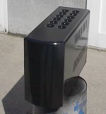
Like I mentioned in my previous post, I made some progress on the case. The outer cover is done except for final paint and to cut the hole for the power switch.
Picture shows the primed case. Several coats of waterbased polyurethane black paint to follow, as soon as the weather is warm enough to spray outdoors. This was sprayed outside, but then quickly brought inside to dry. This primer is solvent based, so will take some time to completely cure.
In the meantime, there's an amp to build.
The +/-70V will be wired point to point with #12 solid copper wire. I was trying to make everything fit - ironic in a case so big. The ten smoothing caps still take up a lot of space (but about half as much as the big ones pictured above). The 12-0-12 transformer is a 2 amp unit so it's not overly large. Pics coming.
Like I mentioned in my previous post, I made some progress on the case. The outer cover is done except for final paint and to cut the hole for the power switch.
Picture shows the primed case. Several coats of waterbased polyurethane black paint to follow, as soon as the weather is warm enough to spray outdoors. This was sprayed outside, but then quickly brought inside to dry. This primer is solvent based, so will take some time to completely cure.
In the meantime, there's an amp to build.
Attachments
MJL21193 said:Another ambitious project! The goal: to build a sub amp that is capable of driving (up to) 1000 watts into a 2 ohm load.
My first comment would that there is a lot of components on the output stage.
I have a 600watt RMS amp that just uses an IRFP240 and IRFP9240 pair. Yes they get hot but they can take 150watts.
I reckon 2 pairs like this on the output with the 100 milli ohm resistors would give around 1000watts RMS and reduce the number of output transistors.
You will need to alter the bias circuit a little to cope with the MOSFETS.
EWorkshop1708 said:VERY NICE.
Have you run it loud yet to see how hot it gets?
Hi EWorkshop,
Thanks. It's still a LONG way from finished, so it still runs pretty cool.
I am still working on power supply components - soft start, etc.My stupidly designed shunt regulator for the 24V supply didn't work as planned, so I've made some changes there. I had gone ahead and made that board (pic below) without realizing the problem. Deleting the zener and routing the caps to ground rather than the rails and I have +/-17.8V (35.6V rail to rail). This I can work with on the soft start board.
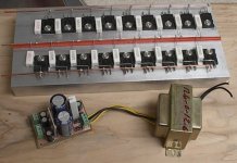
Here's the low voltage power supply board (with transformer) and the output stage with the emitter resistors installed. They are .82 ohm / 5W. These connect to a #12 solid copper wire that runs down the middle of the heatsink. It looks puny, but I don't think it will have any problem handling the current involved.
Attachments
Re: Re: 1000 Watt Sub Amp: Design / Build
Hi,
It would be a smidge counterproductive to undo the output stage that I've built in favour of MOSFETS, don't you think? Besides my moniker, the doctors say I'm not ready to play with MOSFETS yet. Most would say I need to stay away from the BJT's too.
I want ample SOA. With the potential for a supply upgrade at some time in the future, I thought I'd overdo it a bit. Besides, I have lots of MJL's.
Back to the amp schematic. Updated, including all of the changes decided earlier. I have separated the front end, which will be on a circuit board, from the output stage and that's what's pictured below. I haven't started a board layout for this yet - still mired in the power supply purgatory.
nigelwright7557 said:
My first comment would that there is a lot of components on the output stage.
Hi,
It would be a smidge counterproductive to undo the output stage that I've built in favour of MOSFETS, don't you think? Besides my moniker, the doctors say I'm not ready to play with MOSFETS yet. Most would say I need to stay away from the BJT's too.
I want ample SOA. With the potential for a supply upgrade at some time in the future, I thought I'd overdo it a bit. Besides, I have lots of MJL's.
Back to the amp schematic. Updated, including all of the changes decided earlier. I have separated the front end, which will be on a circuit board, from the output stage and that's what's pictured below. I haven't started a board layout for this yet - still mired in the power supply purgatory.
Attachments
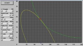
Here are you load lines for 1kW into 2 ohms with 8 pairs of MJL2119(3/4).
With a 45 degree phase shift the 1 sec non temperature-derated SOA is slightly violated.
So, 8 pairs isn't really that over the top for the power rating. For domestic use, with only moderate occasional abuse it should hold up quite well.
With a 45 degree phase shift the 1 sec non temperature-derated SOA is slightly violated.
So, 8 pairs isn't really that over the top for the power rating. For domestic use, with only moderate occasional abuse it should hold up quite well.
Attachments
G.Kleinschmidt said:Here are you load lines for 1kW into 2 ohms with 8 pairs of MJL2119(3/4).
With a 45 degree phase shift the 1 sec non temperature-derated SOA is slightly violated.
So, 8 pairs isn't really that over the top for the power rating. For domestic use, with only moderate occasional abuse it should hold up quite well.
Thanks Glen,
The transformer I have now is a 50-0-50, 850VA unit, so not up to the task for 1000W into 2 ohms. I may get a bigger one in the future if I'm still interested.
Moderate occasional abuse is a given.

Here's the main power PCB that I've laid out. It uses a surplus Omron 20A @ 120 VAC relay. This is a BIG relay, with twin break contacts, spade socket connectors and a 24VDC coil. It has 8 contacts (4 switches). I have two of these and the other one I will use for speaker switching.
This board has the mains fuses as well as the soft start ballast resistors. The soft start board is seperate and it's based on Rod Elliot's design. I will not show the board artwork for it here, as Rod sells these boards.
Attachments
Re: Re: 1000 Watt Sub Amp: Design / Build
did you read Glen's comments on the SOA of the 8pair?
Glen,
what temperature have you used for the SOAR that you posted?
nigelwright7557 said:
My first comment would that there is a lot of components on the output stage.
I have a 600watt RMS amp that just uses an IRFP240 and IRFP9240 pair. Yes they get hot but they can take 150watts.
I reckon 2 pairs like this on the output with the 100 milli ohm resistors would give around 1000watts RMS and reduce the number of output transistors.
You will need to alter the bias circuit a little to cope with the MOSFETS.
Hi Nigel,G.Kleinschmidt said:Here are you load lines for 1kW into 2 ohms with 8 pairs of MJL2119(3/4).
With a 45 degree phase shift the 1 sec non temperature-derated SOA is slightly violated.
So, 8 pairs isn't really that over the top for the power rating. For domestic use, with only moderate occasional abuse it should hold up quite well.
did you read Glen's comments on the SOA of the 8pair?
Glen,
what temperature have you used for the SOAR that you posted?
Re: Re: Re: 1000 Watt Sub Amp: Design / Build
I worked out what I could use from the max dissipation in the MOSFETS. They are 150watts.
Given they are only on for half the time then this gives 300watts per half cycle.
The power dissipation is a little odd when you first look at it because it has a max at half the voltage rail. Clearly at 0V there is no current and at 48v (my amp) iti s another minimum as virtually no volts across the MOSFET.
I reckon at worst case I get 144WRMS into the MOSFET but this has to be divided by 2 as each MOSFET only works on a half cycle.
I reckon I can get 1000WRMS if I pair up the MOSFETS but this would be into 2 ohms and not the current 4ohms I use.
In practice I must admit to be using a massive heatsink which is fan assisted. I ran the power amp with a music signal to just below clipping for half an hour and the MOSFETS get slightly too hot to touch so maybe around 50-60 degrees C and the heatsink stays cool.
The only things I dont like about the MOSFETS is the gate voltage needs to be higher than a bipolar solution. This means I need a higher voltage power rails for the MOSFET solution.
AndrewT said:
Hi Nigel,
did you read Glen's comments on the SOA of the 8pair?
Glen,
what temperature have you used for the SOAR that you posted?
I worked out what I could use from the max dissipation in the MOSFETS. They are 150watts.
Given they are only on for half the time then this gives 300watts per half cycle.
The power dissipation is a little odd when you first look at it because it has a max at half the voltage rail. Clearly at 0V there is no current and at 48v (my amp) iti s another minimum as virtually no volts across the MOSFET.
I reckon at worst case I get 144WRMS into the MOSFET but this has to be divided by 2 as each MOSFET only works on a half cycle.
I reckon I can get 1000WRMS if I pair up the MOSFETS but this would be into 2 ohms and not the current 4ohms I use.
In practice I must admit to be using a massive heatsink which is fan assisted. I ran the power amp with a music signal to just below clipping for half an hour and the MOSFETS get slightly too hot to touch so maybe around 50-60 degrees C and the heatsink stays cool.
The only things I dont like about the MOSFETS is the gate voltage needs to be higher than a bipolar solution. This means I need a higher voltage power rails for the MOSFET solution.
Re: Re: Re: Re: 1000 Watt Sub Amp: Design / Build
Hi,
I lack the expertise to disagree with you, but I strongly feel more than 2 pairs (of anything) are needed for this load.
As I mentioned back in post #9, I used a handy spreadsheet I found at Raymonds Audio to determine the number of output pairs for this amp. This was confirmed by Glen above also.
The MJL21193/4 are 200W devices, so no slouches.
With regards to heat: I want this amp to run silent. It has fans, but I don't want them to come on, except under extreme load. Part of the solution was to use as many outputs on the heatsink that would fit, thereby facilitating fast dissipation.
I have done a board layout for the amps front end. It is very compact (just 45mm x 85mm). The idea is to bolt it to the end of the heatsink, with the copper pads contacting the heatsinks to supply the rail voltage. A fairly elegant solution, if I do say so.
The top copper layer will be a poured ground plan.
nigelwright7557 said:
I reckon I can get 1000WRMS if I pair up the MOSFETS but this would be into 2 ohms and not the current 4ohms I use.
In practice I must admit to be using a massive heatsink which is fan assisted. I ran the power amp with a music signal to just below clipping for half an hour and the MOSFETS get slightly too hot to touch so maybe around 50-60 degrees C and the heatsink stays cool.
Hi,
I lack the expertise to disagree with you, but I strongly feel more than 2 pairs (of anything) are needed for this load.
As I mentioned back in post #9, I used a handy spreadsheet I found at Raymonds Audio to determine the number of output pairs for this amp. This was confirmed by Glen above also.
The MJL21193/4 are 200W devices, so no slouches.
With regards to heat: I want this amp to run silent. It has fans, but I don't want them to come on, except under extreme load. Part of the solution was to use as many outputs on the heatsink that would fit, thereby facilitating fast dissipation.
I have done a board layout for the amps front end. It is very compact (just 45mm x 85mm). The idea is to bolt it to the end of the heatsink, with the copper pads contacting the heatsinks to supply the rail voltage. A fairly elegant solution, if I do say so.
The top copper layer will be a poured ground plan.
Attachments
- Status
- This old topic is closed. If you want to reopen this topic, contact a moderator using the "Report Post" button.
- Home
- Amplifiers
- Solid State
- 1000 Watt Sub Amp: Design / Build