I built recently a DoZ preamp based on Rod Elliott kit (P37A) powered by his P-05-rev B power supply.
http://sound.westhost.com/project05b.htm
The PSU is a standard LM317/397 dual supply but with a twist - it has a AUX voltage output to drive a muting relay.
I had a turn ON thump so the relay was a must. However I did not have any turn OFF noise. I included an output relay where the output is normally shorted and the relay has a delay of around 0.5 sec, just enough to avoid switching noises.
The turn ON thump is gone but I have a sharp thump after switching preamp OFF - looks like from the relay itself. CAn I tweak my relay setup somehow to get rid of this? MAybe a capacitor across the relay supply to slow down its reaction.
That diode is on the relay supply board already, together with a 10uF cap in parallel with the diode.
It seams to me that the shorting of the preamp output causes that - like there is significant level of signal at the output even after the relay delay time. Should I increase the delay? However I am not sure how to do it.
It seams to me that the shorting of the preamp output causes that - like there is significant level of signal at the output even after the relay delay time. Should I increase the delay? However I am not sure how to do it.
I am not the designer - its Rod Elliott's kit - here is his explanation:
"When power is first applied, Q3 is turned on by the charging current of C13. This shorts the base of Q2 and prevents it from turning on, so there is no output. After C13 is charged, Q3 turns off, Q1 and Q2 turn on, and DC is available at the aux output. As soon as AC is removed, C11 discharges rapidly, removing base current from Q1, so Q1 and Q2 turn off, removing the DC. An attached relay will promptly drop out, activating the mute function."
I hope it makes things clearer.
But why there is that noise on power off? CAn it be the relay itself?
I am assuming that you have a seperate power amplifier.
The correct turn on and turn off sequence is as follows:
Turn the preamp on first and after it is stable then turn on the power amplifier and there will be no noise.
Turn off the power amplifier first and allow a few seconds for the power supply to die down and then turn off the preamplifier and no noise will result.
Not being familiar with what you have there I can only make a guess. No need for a relay when the units are powered on and off as I mentioned.
All sounds a bit weird this, just to recap then, you say you have a relay connected across the output of preamp that shorts this output to ground and the relay is in this state with no power supplied (the output reads s/c to ground with all off). You switch on and after delay relay powers up removing short on output. No noise there ? On switch off if the relay instantly shorts output I can't see it's possible to get noise.Possibilties include, 1. A conflict off time constants, does the relay drop out and then pull back in again perhaps for a fraction of second. 2. Relays often have significant contact resistance, is it directly across a low impedance output, try a 100 ohm resistor in series with output before the relay. As Andrew points out it has to be "instant disconnect" which in this case means contacts to close. 3. There is a D.C. offset somewhere and the sudden short perhaps discharges a coupling cap somewhere causing thump.
Regards Karl
Regards Karl
You are right about the relay arrangement and regarding the noise- there is a shot delay on the power On sequence and no noise. There is a short delay on power OFF and there is that thump noise. So, the relay does NOT react instantly. The output impedance of the gain stage is only 300ohm - and that can be defined as low.
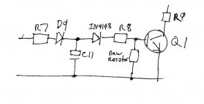
O.K. What I would try is this, first connect a LED + resistor across relay so you can see when it mutes and if it switches cleanly. Without component values, it's a bit hard to say but I think C11 is keeping Q1 turned on to long. Try a smaller cap, perhaps even less than 1mfd depending on the values of R7/8 . You should aim to keep Q1 only just on. If you could tell us values of R7/8 and C11 it would help.You could also try adding a resistor across C11 to speed up discharge.
Karl
Karl
Me again ") Thinking about this, it's not good practice to define the discharge rate by just dumping the charge into a B-E junction. The transistor will linger in no mans land as the base current reduces slowly. Without major mods look at this idea. Not shown on sketch but add resistor across C11.
Thinking about this, it's not good practice to define the discharge rate by just dumping the charge into a B-E junction. The transistor will linger in no mans land as the base current reduces slowly. Without major mods look at this idea. Not shown on sketch but add resistor across C11.
Thinking about this, it's not good practice to define the discharge rate by just dumping the charge into a B-E junction. The transistor will linger in no mans land as the base current reduces slowly. Without major mods look at this idea. Not shown on sketch but add resistor across C11.Attachments
As I understand it, the relay Diode spoken of by Frank Berry isn't the one shown on the schematic.
Scroll down a way to potection diodes on this page...........
http://www.kpsec.freeuk.com/components/relay.htm
John
Scroll down a way to potection diodes on this page...........
http://www.kpsec.freeuk.com/components/relay.htm
John

- Status
- This old topic is closed. If you want to reopen this topic, contact a moderator using the "Report Post" button.
- Home
- Amplifiers
- Solid State
- Muting relay problem