JAZZ2250 said:
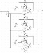
Check the first post of this thread for buffers, active XO, and summing circuits. Be ware that the the connection of buffered output is wrong. The center of the phono connector is signal, not ground. My mistake.
You can find the power amp circuit at the following link:
http://home.attbi.com/~greggbaker/invertedLM3875.gif
thanks, i should have seen that, im blind

Matttcattt said:
thanks, i should have seen that, im blind
No problem at all.
Currently, I'm designing a PCB layout for input buffer, XOs and output buffer. And, regulated power supply of +/-14V will be on the same board to minimize the size. I'll post the picture if you're interested in.
")
Well, I need a sub amp... and want to use the OPA541. I hd another post, but it was suggested that they be combined, so I shall ask here...
My quickly thrown together circuit is attached. I have some questions...
I will be using a +/-28VDC@5A power supply with three ot these things in parallel, each with a gain of 11 (20dB). In theory, this should get me upwards of 300W, though my power supply will crap out at about 140W. Perfectly fine for my app, which only requires 115W or so. Anyway, is it ok to do an unregulated PS here? Just go AC tranny -> 4700uF cap -> 2200uf cap -> 100uF cap -> 1uF film cap --> V+/- out. Would this be ok?
Also, is it ok to hook up the OPA541's the way I have shown? I am skipping the current thingy they have... from pin 8. Can I leave it disconnected, or do I need to connect it to output? Does it require a resistor? What value?
EDIT: What is a good value for a sub potentiometer? (P1 in schem)
Thanks
Attachments
trespasser_guy said:
Also, is it ok to hook up the OPA541's the way I have shown? I am skipping the current thingy they have... from pin 8. Can I leave it disconnected, or do I need to connect it to output? Does it require a resistor? What value?
B]
I don't think you should skip the limiting resistor. Unfortunately the 541 needs a wirewound resistor from pin 8 to the output, instead of a metal film to ground as the 549.
The diagram you show lacks the paralleling resistors at the output of each chip, which should be something like 0.1 or 0.22 , 5w types.
Carlos
Matttcattt said:what do i need to connect to pin 8? what value resistor to the ouput?
Download the datasheet:
http://www-s.ti.com/sc/ds/opa541.pdf
There's a formula on page 6 that tells you how to set that limit.
Carlos
Matttcattt said:what do i need to connect to pin 8? what value resistor to the ouput?
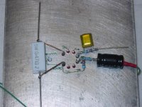
Attached is a photo of the prototype subwoofer amp using OPA541AM mounted on a 1/4" thick aluminum plate. You can see the current limiting resistor which in my case is 0.47Ohm/5W. Basic configuration is an inverting amplifier with a gain of 10.
What I'm wondering is if the current limiting resistor will affect the output signal because the output signal passes through the resistor which is different from OPA549. I'm thinking to do an A/B test with these chips once the PCB for the active crossover is finished.
Attachments
PSU capacitor
Could anybody give me an advice on the capacitance of power supply filtering capacitors? I'll run the amp using +/-25VDC supply voltage. Active crossover will give a gain of 2, and the power amp will give a gain of 10. The subwoofer will be a DVC with nominal impedance of 8 ohms, but it will be connected in parallel. Thanks in advance.
Could anybody give me an advice on the capacitance of power supply filtering capacitors? I'll run the amp using +/-25VDC supply voltage. Active crossover will give a gain of 2, and the power amp will give a gain of 10. The subwoofer will be a DVC with nominal impedance of 8 ohms, but it will be connected in parallel. Thanks in advance.
PSU caps
I monitored +V at the power supply capacitor (10,000 uF) when the amp was playing some music, and found that the +V drops from 25.4 to 23 V momentarilly when the music hits bass loud. So, I guess I need more capacitance at the power supply filtering section. Could anybody give me a hint how I can figure out the right capacitance value? Thanks.
I monitored +V at the power supply capacitor (10,000 uF) when the amp was playing some music, and found that the +V drops from 25.4 to 23 V momentarilly when the music hits bass loud. So, I guess I need more capacitance at the power supply filtering section. Could anybody give me a hint how I can figure out the right capacitance value? Thanks.
No complicated math required
I don't know enough about your transformer to know exactly what it is capable of outputting into the caps - it will drop voltage under load until you buy more than you need - but thats not exactly important here anyhow. Not too much, not too little. I your case, go see the thread for cheap caps in the parts area and get two of the 68KuF 50v caps. At $5 each, they are more than enough for the chip you are using (541 or 549). Use more than that and you have to start worring about in-rush limiting with a thermistor or something.
Don't forget to use fuses!
soft-start
Thanks for your reply, Sawzall.
68,000uF seems to be an overkill for my application, but it sounds okay at the same time. Like you pointed out, I think I'll have to add some sort of soft-start circuit. Do you have any idea about it? Or anybody else? Thanks in advance.
Thanks for your reply, Sawzall.
68,000uF seems to be an overkill for my application, but it sounds okay at the same time. Like you pointed out, I think I'll have to add some sort of soft-start circuit. Do you have any idea about it? Or anybody else? Thanks in advance.
DC split supply
Well...
It seems I don't need to worry about the soft-start circuit because my friend, who is going to take this sub/amp, changed his mind to put these in his CAR. Now, what I'm wondering is
1) if I can use a DC split supply to power the active crossover circuits shown in the first post of this thread. The DC split power supply will consist of two resistors (1k), serially connected from +V to ground, each of which paralleled with 1,000 uF caps as shown in Rod Elliot's website. The virtual ground will be +1/2V (6 volts) provided by the junction of the two resistors.
http://sound.westhost.com/project43.htm
2) and if I can simply put a decoupling cap btwn the crossover and power amp input. If so, what value would do?
I already have a power amplifier (not OPA541/549) to fire the sub. Though it's not a high power one, I think it will be okay power-wise.
- Status
- This old topic is closed. If you want to reopen this topic, contact a moderator using the "Report Post" button.
- Home
- Amplifiers
- Solid State
- DIY subwoofer amp