Hi, Well after having seen all the amazing projects and designs you guys have come up with I thought I would share my design on these pages. First and foremost this was designed for music reproduction in a domestic setting and without wanting to "hijack" another current thread, YES amplifiers do sound different, that is why I spent so much time in the development of this one. This amp is without doubt "musical" in all the best sense of that term, it's ability to recreate a believable soundstage is absolutely compelling. If anyone is interested in what it looks like and further details there are some pictures in the "Post your solid state pics here" forum. (About post 283) The thinking behind this project draws on the work of the late John Linsley Hood whose designs and thinking I much admired.
26th August 2024. LTspice simulation files added. These include Renesas and Exicon Double Die models and should click and run on the current version of LTspice.
Also included is squarewave testing. Alter the .par line to suit. tr = risetime, f = frequency and vp = amplitude. The sim should scale automatically to accommodate these settings. The squarewave starts at 0.00 volts and so the output should be symmetrically centred around 0v.
The sim called 'Startup Behaviour' shows the operation of the servo and why the speaker delay circuit is essential. After 3 seconds a 1kHz signal is applied and output. The delay should be around 5 or more seconds to get a totally silent switch on.
--------------------------------------------------------------------------------------------------------------------------------------------------------
This index of the thread should help you find the relevant important notes and general information.
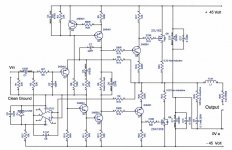
1. The circuit diagram in this, post #1 is correct. The only omission is a 10 ohm 2 watt carbon/metal film across the output coil.
2. The TL071 opamp must not be substituted. This type works correctly on the single negative 12 volt rail. Other device types may not do so.
3. A speaker relay incorporating a switch on delay is essential due to the action of the servo and the single ended input stage. This can be extremely simple consisting of a FET, a C-R network and relay. Post #273 in another thread shows the idea of solid state relays developed into a working example. Credit for the idea of the SS relay goes to those mentioned in that thread.
My MOSFET amplifier designed for music. - Page 14 - diyAudio
4. alex mm' brilliant PCB designs. Post #300
My MOSFET amplifier designed for music. - Page 15 - diyAudio
5. The FET pinouts, post #113
My MOSFET amplifier designed for music. - Page 6 - diyAudio
6. Squarewave testing, posts #157 to 161
My MOSFET amplifier designed for music. - Page 8 - diyAudio
7. Heatsinks, post #164
My MOSFET amplifier designed for music. - Page 9 - diyAudio
8. A glowing endorsement, post #186 and this,
http://www.diyaudio.com/forums/soli...-amplifier-designed-music-10.html#post1567427
9. Spicing it up... LTspice files, post #312
http://www.diyaudio.com/forums/soli...-amplifier-designed-music-16.html#post3171018
10. And finally some of my benchmarks and my thoughts on how it sounds. The adventures of getting the design to where it stands today, post #107
http://www.diyaudio.com/forums/soli...t-amplifier-designed-music-6.html#post1539997
11. Further development of the design using parallel output devices to improve current delivery into adverse or low impedance loads. Circuit details and PCB layouts are in post #904
My MOSFET amplifier designed for music.
12. Gerber Files and BOM for an SMD version of this amp. Design and development of the boards by @geoffw1 are in post #1678
Gerber Files and BOM for SMD version
-------------------------------------------------------------------------------------------------------------------------------------------------------
26th August 2024. LTspice simulation files added. These include Renesas and Exicon Double Die models and should click and run on the current version of LTspice.
Also included is squarewave testing. Alter the .par line to suit. tr = risetime, f = frequency and vp = amplitude. The sim should scale automatically to accommodate these settings. The squarewave starts at 0.00 volts and so the output should be symmetrically centred around 0v.
The sim called 'Startup Behaviour' shows the operation of the servo and why the speaker delay circuit is essential. After 3 seconds a 1kHz signal is applied and output. The delay should be around 5 or more seconds to get a totally silent switch on.
--------------------------------------------------------------------------------------------------------------------------------------------------------
This index of the thread should help you find the relevant important notes and general information.
1. The circuit diagram in this, post #1 is correct. The only omission is a 10 ohm 2 watt carbon/metal film across the output coil.
2. The TL071 opamp must not be substituted. This type works correctly on the single negative 12 volt rail. Other device types may not do so.
3. A speaker relay incorporating a switch on delay is essential due to the action of the servo and the single ended input stage. This can be extremely simple consisting of a FET, a C-R network and relay. Post #273 in another thread shows the idea of solid state relays developed into a working example. Credit for the idea of the SS relay goes to those mentioned in that thread.
My MOSFET amplifier designed for music. - Page 14 - diyAudio
4. alex mm' brilliant PCB designs. Post #300
My MOSFET amplifier designed for music. - Page 15 - diyAudio
5. The FET pinouts, post #113
My MOSFET amplifier designed for music. - Page 6 - diyAudio
6. Squarewave testing, posts #157 to 161
My MOSFET amplifier designed for music. - Page 8 - diyAudio
7. Heatsinks, post #164
My MOSFET amplifier designed for music. - Page 9 - diyAudio
8. A glowing endorsement, post #186 and this,
http://www.diyaudio.com/forums/soli...-amplifier-designed-music-10.html#post1567427
9. Spicing it up... LTspice files, post #312
http://www.diyaudio.com/forums/soli...-amplifier-designed-music-16.html#post3171018
10. And finally some of my benchmarks and my thoughts on how it sounds. The adventures of getting the design to where it stands today, post #107
http://www.diyaudio.com/forums/soli...t-amplifier-designed-music-6.html#post1539997
11. Further development of the design using parallel output devices to improve current delivery into adverse or low impedance loads. Circuit details and PCB layouts are in post #904
My MOSFET amplifier designed for music.
12. Gerber Files and BOM for an SMD version of this amp. Design and development of the boards by @geoffw1 are in post #1678
Gerber Files and BOM for SMD version
-------------------------------------------------------------------------------------------------------------------------------------------------------
Attachments
-
 final.jpg82.6 KB · Views: 39,550
 -
M1 1Khz 1 Watt FFT Simulation plus Servo Plus Exicon Models.asc11.4 KB · Views: 207
-
M1 1Khz 1 Watt FFT Simulation plus Servo Plus Renesas Models.asc11.3 KB · Views: 120
-
M1 1Khz 1 Watt FFT Simulation plus Servo Plus Renesas Models Squarewave Test.asc11.3 KB · Views: 121
-
M1 Start Up Behaviour.asc11.7 KB · Views: 122
Last edited:

This is the Preamp in outline form (I am only just getting to grips with a PCB Software package) all the original work was hand drawn. The series /shunt switching works brilliantly and give total isolation between inputs. Even with something ridiculous like a 10volt peak/peak squarewave as an input, there is no audible breakthrough even with volume on max.
Attachments

darkfenriz said:
... and C3
Hi Darkfenriz, how are you? 🙂
I agree , the servo is "in charge" of taking care of the offset...
Anyway, C3 in the schematic is with the polarity inverted... 😉
Hi Tube_Dude, you know, I wondered that at the time, my reason for including them was to provide more? if thats the right word isolation for the MOSFET's . They do reduce efficiency though. I would like to develop this design further, possibly running the front end (Up to Q3 and Q5) on a higher rail with shunt regulation (Power supply rejection is one area that could be improved).
Darkfenriz, wish I could do away with the electrolytic in the feedback arm, as you say the servo is in charge, but the base voltage of Q1 is around -6volts, so C3 is unfortunately needed (polarity is correct on circuit with about 5 volts across it) . That's the price you pay for using a single ended input stage but one that's well worth it. The TL071 works fine with only a single negative rail in this application, many other Op-Amps won't and would need + & - supply.
Thanks for the input
Karl
Molly
the -6V on Q1 base will go up closer to zero if you remove the capacitor, like -1.5V or so...
the -6V on Q1 base will go up closer to zero if you remove the capacitor, like -1.5V or so...
nice
OK now we need someone to design a PCB 😉.
I have tried designing a few using ExpressPCB but it seems to end up a mess!
I have many of the 2sk1058/j162 waiting for something like this!!
OK now we need someone to design a PCB 😉.
I have tried designing a few using ExpressPCB but it seems to end up a mess!
I have many of the 2sk1058/j162 waiting for something like this!!
Hi, I don't think to be honest it's quite that easy, (oh by the way whose Molly 😉 ) the operating point of Q1 would be shifted away from it's linear region. With higher values of R7 what you suggest would work, but as R7 is reduced, decreasing the global feedback, the servo would not compensate. Think of an "old" A.C. coupled design on a single rail with a pot to set the "mid point" voltage of the output transistors. If you shorted the equivalent cap in an amp like this you could never readjust the midpoint to compensate. This design more closely resembles this configuration. Thanks for you're interest, I think even some of the "Tube" fans out there would be suprised how musically engaging this amp is.
Thanks again Karl
Thanks again Karl
Hi Mike, The original P.C.B.'s were all hand-drawn one offs unfortunately. Now P.C.B. layout is another subject on it's own, and layout and correct grounding is vital to get the best performance. I will say this though, designs like this are far more "docile" to work with than many of the more complex (I am thinking of what are really discrete power opamps here). I can't help but feel this stability is one reason why it does sound so good. When making a stereo amp with a single P.S.U. I could never quite "get my head around" the best or ideal grounding configuration. The problem is that while it is easy for one amp(channel) with one P.S.U. I could never reconcile what happens when the two signal grounds (Left and right) are connected together at the input which at some point they must. I know there are various techniques used e.g. a "ground lift resistor" to overcome these problems but I was not happy with any. In the end I actually built a model consisting of two OpAmps on two P.C.B.'s which represent the two channels. I used 10 ohm resistors in the ground leads to highlight and get a feel for what really happens when each channel is supplying a different signal to there respective load. Doing this I came up with a scheme that eliminates as much as possible any interaction.
Regards Karl
Regards Karl
Greetings,
I'm interested with your amplifier.
if you don't mind can you send me the photo of your current amplifier layout?
many thanks and best rgds,
I'm interested with your amplifier.
if you don't mind can you send me the photo of your current amplifier layout?
many thanks and best rgds,
Hi Dexter & Eyoung, Thanks for you're interest in this amp, as mentioned at the start, this was built and designed pre p.c. (for me anyway) and all the layouts really were one off's. Have a close look at the pictures I mention, the power amp modules were designed to fit those metal "cans". on quite small boards. The cans were actually P.S.U.s from the Sony C9 Betamax and were ideal for my use as they also include that heatsink at the rear of each one. I designed the board to be an exact fit replacement and even the MOSFET.s fit into the original places that the P.S.U. chopper transistors fitted. Everything is extremely tightly screwed together, and integrated into the case. But 😉 I am playing around with a P.C.B. software package at the moment so there is yet hope. To be continued !
Regard Karl.
Regard Karl.
Hi Mooly
I had a friend of mine have a look at your schematic and he made some nice comments which I thought you might like to read. They are as follows ...
I had a friend of mine have a look at your schematic and he made some nice comments which I thought you might like to read. They are as follows ...
🙂nice design!
Yes this is indeed a sort of Linsley Hood breed.
I built one of his famous amps designed back in 1969, a 10 W class A amp with very transparent sound sonics.
This Mooly Amp draws from the tight grip on the non-linearities of the output stage, keeping them under control by heavy local NFB. The non-linearities usually account for the spectral spray of THD and IM signals. So, keeping them well under control makes the amp sound rather nice.
The input stage is quite a bit outdated and a true copy of Hood's design, added a servo loop to get rid of the Vbe offset.
Hello KLe,
Thank you for posting your friends thought's on my design-- you must thank them from me. " The Mooly Amp " wonder what that would look like silk screened on the front --- that could be the next big seller 😀
The amp though in all seriousness, it's not just good sonically, it's absolutely marvellous, better than anyone would expect from a quick look at the circuit. THE MUSIC LIVES. No other words to describe it. Someone PLEASE PLEASE build it and shout to the world how good it sounds.
Karl
Hi MoolyMooly said:... The amp though in all seriousness, it's not just good sonically, it's absolutely marvellous, better than anyone would expect from a quick look at the circuit. THE MUSIC LIVES. No other words to describe it. Someone PLEASE PLEASE build it and shout to the world how good it sounds.
Karl
Did you do/have a PCB for your amp?
If so, do you have any spare ...
I would be happy to buy 2 from you and build it ...
🙂
Hi,
Erm-- A few have asked this 🙂 . As I have said earlier the originals were one off's in the truest sense-- have a look at the pics I mentioned at the start.
The best I can offer I am afraid is an untested layout-- which was really an exercise in using DipTrace for me. Having said that the whole design is extremely stable and not prone to any "nasties" and even on prototyping board it performs well, and I can not see any major problems with using this layout.
Attachments

Mooly,
it`s easy, isn`t it...just to follow the successful path of great sounding English topologies.
Did you experience oscillations in the output? How did you determine R13/18?
it`s easy, isn`t it...just to follow the successful path of great sounding English topologies.
Did you experience oscillations in the output? How did you determine R13/18?
- Home
- Amplifiers
- Solid State
- My MOSFET amplifier designed for music