I've added an index to post #1 to help find the important parts of the thread.
http://www.diyaudio.com/forums/solid-state/119151-my-mosfet-amplifier-designed-music.html
Thank you, Mooly, for the above. I wish all thread starters do this.
I am interested in a pair of the PCBs if the purchase goes through!
Thank you, Mooly, for the above. I wish all thread starters do this.
I am interested in a pair of the PCBs if the purchase goes through!
Thanks... all thread starters have that option available as a "first post edit"
Cool Mooly, I pm Alex and tell him the interest in using his files. If he agrees then I can go ahead and order. I will pick up the 20 but if there are more demand it might make sense to ask everybody and if there is more demand then they can pay for theirs but to order them all together. I assume these files that Alex has are Gerber files this is what the PCB manufacturer askes for: "gerber 274X+NC drill files and BOM".
Alex, that's great.
If I post a couple of sugestions on the PCB (the first one you did way back yonder") ) could you see what you think.
) could you see what you think.
I'm thinking it might be beneficial to have the input ground and the PSU/Zobel ground as separate points that can be run back to the main PSU to avoid any channel interaction for a stereo pair on a single supply.
What do you think ?
If I post a couple of sugestions on the PCB (the first one you did way back yonder
) could you see what you think.I'm thinking it might be beneficial to have the input ground and the PSU/Zobel ground as separate points that can be run back to the main PSU to avoid any channel interaction for a stereo pair on a single supply.
What do you think ?
Alex / Mooly, Great appreciate your reworking and there is no hurry from my side.
Alex, the pcb company specified they only work with Gerber274X and NC drill files which we have to email them.
Now that this is pcb board this will probably interest with many less experienced guys like myself whom want to build the amp.
Alex, the pcb company specified they only work with Gerber274X and NC drill files which we have to email them.
Now that this is pcb board this will probably interest with many less experienced guys like myself whom want to build the amp.
Alex / Mooly, Great appreciate your reworking and there is no hurry from my side.
Alex, the pcb company specified they only work with Gerber274X and NC drill files which we have to email them.
Now that this is pcb board this will probably interest with many less experienced guys like myself whom want to build the amp.
John - I am interested...
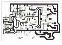
I'm trying a rework of a layout I did some time ago based on this image that incorporates the important points of correct NFB take off point and also the ability to use two ground return leads to the PSU. Two returns keeps the signal ground separate and avoids channel interaction in a stereo pair fed from a common PSU.
Attachments
Hi Dudaindc, great your are interested, I put your rubycon caps to good use in several projects.
We will keep a running list, but not sure how how this will be organized except proceeds to DIYaudio and I think Mooly wanted to offer to guys whom were in the thread starters as first option, but will put you on the list. I assume you want two boards for a stereo.
Till now Gannagi, post 341 2 boards,
Dudaindc post 347 2 boards,
Mooly some boards?
Alex MM some boards?
Thread Starters?
Anyone else interested just post your interest and I guess we will go from there. It looks like Mooly is reworking his design to use a common psu, which is a good idea to keep costs down.
Lets see where we get to with the layout first.
I'm using Diptrace which is freeware and I will post the Diptrace files so anyone can open and modify anything as they wish. It does have Gerber files as an option but what you need and do with all the options in there I haven't a clue.
This needs someone who has the knowledge and experience of all thats needed to take a "design" and produce the required files needed. All my boards are handmade "one-offs"

Hi Dudaindc, great your are interested, I put your rubycon caps to good use in several projects.
We will keep a running list, but not sure how how this will be organized except proceeds to DIYaudio and I think Mooly wanted to offer to guys whom were in the thread starters as first option, but will put you on the list. I assume you want two boards for a stereo.
Till now Gannagi, post 341 2 boards,
Dudaindc post 347 2 boards,
Mooly some boards?
Alex MM some boards?
Thread Starters?
Anyone else interested just post your interest and I guess we will go from there. It looks like Mooly is reworking his design to use a common psu, which is a good idea to keep costs down.
Please correct my name to Gannaji. Thank you for your efforts.
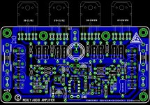
I've printed the board out to scale and find we're a bit tight on real estate. The high wattage resistors (the 0.22 ohm) and the PSU caps would be similar in size to the parts in the picture. The small resistor is a normal 0.5/0.6 watt metal film.
(I feel really terrible saying this after all the hard work Alex puts in on this because the boards are spectacular. Have I missed something here with the part sizes)
The board layout is good. All I would perhaps alter is the NFB takeoff point which can be done easily and maybe look splitting the grounds... at least to give the option. I'll look at that more.
(I feel really terrible saying this after all the hard work Alex puts in on this because the boards are spectacular. Have I missed something here with the part sizes
) The board layout is good. All I would perhaps alter is the NFB takeoff point which can be done easily and maybe look splitting the grounds... at least to give the option. I'll look at that more.
Attachments
 Iv'e been told
the default for 1/4W resistors on my software is also 0.4 in.
but I like to give warmer resistors some room to breathe, Im novice though.
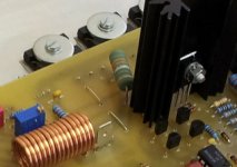
Picture is how I fitted 5W on same situation on APEX SR200 3.1 board
Attachments
Last edited:
Wow alex, that was real nice job you did. Better let the specialists comment on the layout as thats above my head, but from a visual point its beautiful and I can see from your design it will be easy to correctly populate the board.
Looks like we are a lot closer to getting some pcb made, appreciate the effort as I am sure everyone does.
I am out for a few days till end of week but when you guys are ready with some final files on an agreed upon layout by those with more technical knowledge than myself, I am happy to put in order for as originally proposed. I added Marco's interest post 354 to the list.
- Home
- Amplifiers
- Solid State
- My MOSFET amplifier designed for music