I thought I had covered this somewhere....
")
something odd with that link though because I wouldn't have picked something looking like that although the description says 'Radial' which means round and then it says thick film... odd.
Links can change and go out of date quickly on supplier sites.
You want a normal round 2 watt carbon or metal film part.
Doug Selfs recommend will cover testing higher powered amplifiers at higher frequencies. If you tested at 40kHz sine you would need a 3 watt part for my amp. Test at higher still frequency and the wattage needed shoots up.
2 watt rating won't even get warm with music blasting out
Attachments
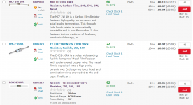
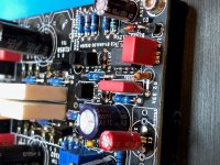
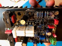
You can see the exact ones in these pictures:
Output Relays
Output Relays
Attachments
for normal music listening with correct build, you can get away with 1 W.
just see if it gets hot...,if it does, then somethings wrong with build/wiring mate!... you may also hear some kind of hiss on your speakers if thats the case...
P.S.: but go with Mooly's suggestion if you want exact build that gives service over many many years.
just see if it gets hot...,if it does, then somethings wrong with build/wiring mate!... you may also hear some kind of hiss on your speakers if thats the case...
P.S.: but go with Mooly's suggestion if you want exact build that gives service over many many years.
Last edited:
Hi prasi,
First of all, thanks to Mooly for designing such an excellent amp circuit. I am very interested in this amp circuit and downloaded the PCB layout you posted. I really like it,it is reasonable and beautiful. May I modify your layout to adapt it to my electronics and make it more compact?
First of all, thanks to Mooly for designing such an excellent amp circuit. I am very interested in this amp circuit and downloaded the PCB layout you posted. I really like it,it is reasonable and beautiful. May I modify your layout to adapt it to my electronics and make it more compact?
Hello Mooly, i am planning on building your amplifier. however the transformer i have is only 2 x 24 vac. So it will give about +/- 33 vdc.
The exact schematic and pcb corresponds to the one that Marc (bandol83) built. post # 904 My MOSFET amplifier designed for music.
Now, is there any need to change certain values of components based on above psu voltage?
regards
prasi
The exact schematic and pcb corresponds to the one that Marc (bandol83) built. post # 904 My MOSFET amplifier designed for music.
Now, is there any need to change certain values of components based on above psu voltage?
regards
prasi
The only thing I can of changing would be the 10k feeding the TL071. You will probably need to drop it to allow the Zener to regulate.
The 10k I used originally only allows around 3.5 milliamps to flow... the opamp takes around 1.5ma leaving the rest for the Zener. So you need to keep that kind of ratio, mainly to minimise power wastage and minimise heat dissipation.
33 volts would need a 5k6 or thereabouts.
The 10k I used originally only allows around 3.5 milliamps to flow... the opamp takes around 1.5ma leaving the rest for the Zener. So you need to keep that kind of ratio, mainly to minimise power wastage and minimise heat dissipation.
33 volts would need a 5k6 or thereabouts.
Hi, Well after having seen all the amazing projects and designs you guys have come up with I thought I would share my design on these pages. First and foremost this was designed for music reproduction in a domestic setting and without wanting to "hijack" another current thread, YES amplifiers do sound different, that is why I spent so much time in the development of this one. This amp is without doubt "musical" in all the best sense of that term, it's ability to recreate a believable soundstage is absolutely compelling. If anyone is interested in what it looks like and further details there are some piccys in the "Post your solid state pics here" forum. (About post 283) The thinking behind this project draws on the work of the late John Linsley Hood whose designs and thinking I much admired.
--------------------------------------------------------------------------------------------------------------------------------------------------------
This index of the thread should help you find the relevant important notes and general information.
1. The circuit diagram in this, post #1 is correct. The only omission is a 10 ohm 2 watt carbon/metal film across the output coil.
2. The TL071 opamp must not be substituted. This type works correctly on the single negative 12 volt rail. Other device types may not do so.
3. A speaker relay incorporating a switch on delay is essential due to the action of the servo and the single ended input stage. This can be extremely simple consisting of a FET, a C-R network and relay. Post #273 in another thread shows the idea of solid state relays developed into a working example. Credit for the idea of the SS relay goes to those mentioned in that thread.
My MOSFET amplifier designed for music. - Page 14 - diyAudio
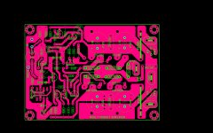
4. alex mm' brilliant PCB designs. Post #300
My MOSFET amplifier designed for music. - Page 15 - diyAudio
5. The FET pinouts, post #113
My MOSFET amplifier designed for music. - Page 6 - diyAudio
6. Squarewave testing, posts #157 to 161
My MOSFET amplifier designed for music. - Page 8 - diyAudio
7. Heatsinks, post #164
My MOSFET amplifier designed for music. - Page 9 - diyAudio
8. A glowing endorsement, post #186 and this,
http://www.diyaudio.com/forums/soli...-amplifier-designed-music-10.html#post1567427
9. Spicing it up... LTspice files, post #312
http://www.diyaudio.com/forums/soli...-amplifier-designed-music-16.html#post3171018
10. And finally some of my benchmarks and my thoughts on how it sounds. The adventures of getting the design to where it stands today, post #107
http://www.diyaudio.com/forums/soli...t-amplifier-designed-music-6.html#post1539997
11. Further development of the design using parallel output devices to improve current delivery into adverse or low impedance loads. Circuit details and PCB layouts are in post #904
My MOSFET amplifier designed for music.
-------------------------------------------------------------------------------------------------------------------------------------------------------
hi mooly ,nice build . is this amp,s sound quality like ampex fx8 or is it higher?
Bias unstable
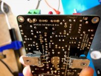
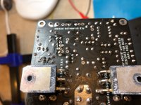
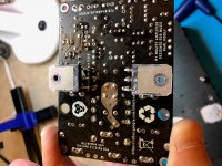
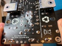
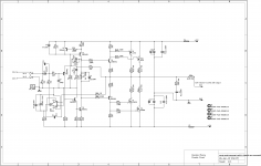
Writing for some assistance troubleshooting this amplifier. It appears to be oscillating, because I cannot get the bias to stabilize. I have checked all resistors, zener and polarity of Caps. I have tried with 1 and 2 pair of outputs installed. I have even pulled mosfets from a working amp, to make sure I have genuine outputs.
I ordered Prasi's 2-pair output boards from China and all my parts are from Mouser or a trusted vendor. I did originally use Chinese sourced 2n5401 and 2N5551 - which were later changed to Mouser parts when it was giving me trouble.
The issue is that the bias is sporadic and when turning the 1k pot (tried the original 500R too with same results) it goes from 25mV to 150 to 250, then back to 12mV and bounces all around. Mesuring bias by voltage drop across 1R 10W resistors in line with the +/-40V rails for testing and setting the bias - cannot get bias to be stable (tried bias from 50mA up to 250mA).
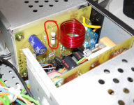
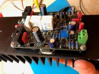
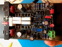
Hopefully these pictures are clear and enough detail for someone to assist me.
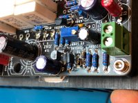
Test setup:
I am running +/-40V rails and have 40,000uF caps.
I populated the board per the schematic (increased voltage on caps as needed - I plan to use +/-50V rails with 2-pair outputs when I get the amp stable during testing)
I do have the 150pF cap populated, as well as the 680k feedback resistor.
Measurements - the only big difference I can see from the voltages provided by Mooly, is my TL071 has a -4.66V from pin 6, where Mooly's spice file has -5.62. I do have the -12V supply and tested all small-signal transistors to be good (no shorts)
Let me know if you see any issues - or need me to run any tests
edit - added schematic as built
Writing for some assistance troubleshooting this amplifier. It appears to be oscillating, because I cannot get the bias to stabilize. I have checked all resistors, zener and polarity of Caps. I have tried with 1 and 2 pair of outputs installed. I have even pulled mosfets from a working amp, to make sure I have genuine outputs.
I ordered Prasi's 2-pair output boards from China and all my parts are from Mouser or a trusted vendor. I did originally use Chinese sourced 2n5401 and 2N5551 - which were later changed to Mouser parts when it was giving me trouble.
The issue is that the bias is sporadic and when turning the 1k pot (tried the original 500R too with same results) it goes from 25mV to 150 to 250, then back to 12mV and bounces all around. Mesuring bias by voltage drop across 1R 10W resistors in line with the +/-40V rails for testing and setting the bias - cannot get bias to be stable (tried bias from 50mA up to 250mA).
Hopefully these pictures are clear and enough detail for someone to assist me.
Test setup:
I am running +/-40V rails and have 40,000uF caps.
I populated the board per the schematic (increased voltage on caps as needed - I plan to use +/-50V rails with 2-pair outputs when I get the amp stable during testing)
I do have the 150pF cap populated, as well as the 680k feedback resistor.
Measurements - the only big difference I can see from the voltages provided by Mooly, is my TL071 has a -4.66V from pin 6, where Mooly's spice file has -5.62. I do have the -12V supply and tested all small-signal transistors to be good (no shorts)
Let me know if you see any issues - or need me to run any tests
edit - added schematic as built
Attachments
Last edited:
- Home
- Amplifiers
- Solid State
- My MOSFET amplifier designed for music