Wouldn't the gain of Q1 increase if R10 (6.8K) was removed and a resistor placed between base emitter of Q2 ? Lower value of course since the voltage across it is now only about 0.6 V or so. The collector of Q1 would see a higher load than 6.8K.
I'll try it later when I have some free time. Thanks Mooly for posting the .asc files.
I'll try it later when I have some free time. Thanks Mooly for posting the .asc files.
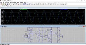
I just tried it quickly with a 1k and the results are pretty similar. The original configuration comes out with fractionally higher open loop gain, only a couple of db at most though. This is with 35uV input voltage @ 1kHz
I can confirm that the amp works fine and sounds very fine with 1K in the feedback resistor position.
The resulting CL gain is much more satisfactory in my system.
I will try HD's nested feedback suggestion in due course.
Hello Mooly,
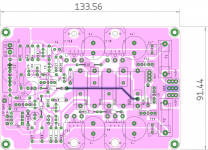
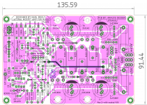
Here is a version of your amp. (I hadn't made a layout for an amp for some time, so what better amp than this one.). There are many layouts for this amp, nice ones by Alexmm.
The corner mounting holes can be omitted as mosfets are nearly in center.
Because of the width of PCB, a 3U case is more suitable for vertical mounting on side-heatsinks.
I am thinking of putting a ground plane on top. What are your views, please suggest.
I am a bit worried about the length of trace from R15 to pin-2 of op-amp, is it too long ?.
?.
needs a bit of clean-up/touch-up with regard to niceness. Although size a bit on the higher side, I tried to maintain larger copper clearances and sparse placements of the components.
Regards
Prasi
P. S. The links in post 1 don't seem to work for me, though it may be just be me.
Here is a version of your amp. (I hadn't made a layout for an amp for some time, so what better amp than this one.). There are many layouts for this amp, nice ones by Alexmm.
The corner mounting holes can be omitted as mosfets are nearly in center.
Because of the width of PCB, a 3U case is more suitable for vertical mounting on side-heatsinks.
I am thinking of putting a ground plane on top. What are your views, please suggest.
I am a bit worried about the length of trace from R15 to pin-2 of op-amp, is it too long
?. needs a bit of clean-up/touch-up with regard to niceness. Although size a bit on the higher side, I tried to maintain larger copper clearances and sparse placements of the components.
Regards
Prasi
P. S. The links in post 1 don't seem to work for me, though it may be just be me
.Attachments
Last edited:
That looks good 
The print to the opamp is fine because pin 2 is at a low impedance due to the integrator action of C8.
Personally I wouldn't use a ground plane for low frequency audio like this, and in fact may cause more problems than it solves. Tying circuit grounds to a plane would result in unpredictable interactions because of the finite impedance of the plane... it might be low but its not zero.
The links work for me but I see they have page numbers embedded within them, so if you use anything other than the default forum page setting then you might end up at the wrong place. I'll see if they are easily fixable in the next few days.
Thanks for your suggestions and clarification. I will remove the top ground layer.
I will keep working on the layout and post gerbers / pdfs here for anyone interested to build.
For the i/p cap, I had this EVOX cap in mind (22.5mm pitch) while making layout.
regards
Prasi
I will keep working on the layout and post gerbers / pdfs here for anyone interested to build.
For the i/p cap, I had this EVOX cap in mind (22.5mm pitch) while making layout.
regards
Prasi
Last edited:
forgot the link, too late to edit
this cap
https://in.rsdelivers.com/product/k...-polyester-capacitor-pet-40-v-ac-63-v/2980223
this cap
https://in.rsdelivers.com/product/k...-polyester-capacitor-pet-40-v-ac-63-v/2980223
So what is your conclusion?
So how does the Mooly compare to the other amps? Quite interested to hear how the Mooly compares to the P101 and MRJ.
Regards ...
I can confirm that the amp works fine and sounds very fine with 1K in the feedback resistor position.
So how does the Mooly compare to the other amps? Quite interested to hear how the Mooly compares to the P101 and MRJ.
Regards ...
The MMAMFM is more involving to listen to than either the P101 or the MRJ**. It is more coherent and offers a better sense of being in an acoustic space. It nails the tune, rythym and musical interplay in a way that defeats many amps.
The MyREF FE is the closest to the Mooly amp in sound. Both these two can "do" female vocals e.g. Wailin' Jennys in a way that sends shivers down your neck.
** I ought to try the MRJ again because I made a couple of changes to my system since I last had a go with it.
I ought to drag my ancient ESP AKSA 55 out of the kitchen system for a test, as well.
You will find the MMAMFM superior to my old AKSA, Dave. I saw that the instant I examined the schematic. And if you make the nested fb resistor I mentioned you will bring it up another level........ Mooly is to be congratulated on nailing something that took me almost twenty years.
Hugh
Hugh
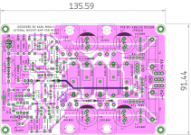
Here are the diy files and gerbers. Special logo for the designer based on his avatar.
PR9372 1/2W and Vishay RN60 series resistors can be easily fitted for small resistors.
For the big 5W'ers, one could use KOA BPR non-inductive or Vishay MRA-05 OR MRA 10 can be fitted , so can many other/similar ones both axial or radial non-inductive ones.
The big decoupling caps can be 7.5mm pitch-18mm dia or 5mm pitch 13mm dia.
regards
Prasi
.PR9372 1/2W and Vishay RN60 series resistors can be easily fitted for small resistors.
For the big 5W'ers, one could use KOA BPR non-inductive or Vishay MRA-05 OR MRA 10 can be fitted , so can many other/similar ones both axial or radial non-inductive ones.
The big decoupling caps can be 7.5mm pitch-18mm dia or 5mm pitch 13mm dia.
regards
Prasi
Attachments
Last edited:
Nice PCB layout Prasi!
Just a couple of thoughts:
Do you need fuses on board if you need a separate delayed-on circuit? You can do overcurrent protection with UPC1237 as well as DC offset protection.
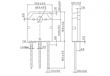
Are the lead bends for the output FETs a bit too close to the package?
Cheers,
Dave
Oh... and why not add a slot for Hugh's nested f/b resistor (across C7)?
Just a couple of thoughts:
Do you need fuses on board if you need a separate delayed-on circuit? You can do overcurrent protection with UPC1237 as well as DC offset protection.
Are the lead bends for the output FETs a bit too close to the package?
Cheers,
Dave
Oh... and why not add a slot for Hugh's nested f/b resistor (across C7)?
Thanks Dave for your suggestions.
Fuses are optional, one can replace them with solid 1.5mm wire.
The fet package I used in this layout needs 7 mm length of the lead from the base of the package to the bottom pad of pcb, add 1.6 mm thick pcb + another 1-1.5 mm or so for top side protrusion, so total of ~10mm min out of 18mm total lead length of package. I used this before for many designs/ builds (built by others too) and never any problems.
Yes, I will add the nested fb resistor for the C7, suggested by Hugh or in the posted design, one can simply solder it from the bottom. I just followed Mooly's original design and an extra pair of fet.
regards
Prasi
.Fuses are optional, one can replace them with solid 1.5mm wire.
The fet package I used in this layout needs 7 mm length of the lead from the base of the package to the bottom pad of pcb, add 1.6 mm thick pcb + another 1-1.5 mm or so for top side protrusion, so total of ~10mm min out of 18mm total lead length of package. I used this before for many designs/ builds (built by others too) and never any problems.
Yes, I will add the nested fb resistor for the C7, suggested by Hugh
or in the posted design, one can simply solder it from the bottom. I just followed Mooly's original design and an extra pair of fet.regards
Prasi
Attachments
Nested FB resistor option
Here is the version with nested FB resistor as suggested by Hugh.
Regards
Prasi
Here is the version with nested FB resistor as suggested by Hugh.
Regards
Prasi
Attachments
- Home
- Amplifiers
- Solid State
- My MOSFET amplifier designed for music