hi Mooly,
Just had a look at your layout in post #19...
Shouldn't the speaker OV return go to the PSU star point not to the PCB? Seems to me that your method will suffer from common impedance coupling to the input caused by the current flowing in the wire from the speaker 0V on the PCB to the star point.
Just had a look at your layout in post #19...
Shouldn't the speaker OV return go to the PSU star point not to the PCB? Seems to me that your method will suffer from common impedance coupling to the input caused by the current flowing in the wire from the speaker 0V on the PCB to the star point.
hi mooly,
i am a bit confused about somethings. output having some voltage it is about 5.6v and showing without connecting the speaker, showing -v on the positive output line, isn't it funny? when i connect the speaker the output voltage come down to 0.++ . do you think it is a problem?
i think its a problem. but across the R21 & R18 voltage showing 0.0+....its looks ok..
need comments pls.
Hello Michael,
If the voltage at the output is Zero with speaker attached but has a voltage without the speaker it could be a stability problem caused by all those wires. Did you move the 270 ohm resistors onto the legs of the FET's. You will not measure any voltage ACROSS R21 and R18. No D.C. current ever flows into the gates of the FET's.
This is where you really need a 'scope Michael. One other thing, have you got the Zobel network connected to the correct side of L1. Also, when the DC voltage was there did the resistor R25 in the zobel network get warm.
I have your other message as well")
If the voltage at the output is Zero with speaker attached but has a voltage without the speaker it could be a stability problem caused by all those wires. Did you move the 270 ohm resistors onto the legs of the FET's. You will not measure any voltage ACROSS R21 and R18. No D.C. current ever flows into the gates of the FET's.
This is where you really need a 'scope Michael. One other thing, have you got the Zobel network connected to the correct side of L1. Also, when the DC voltage was there did the resistor R25 in the zobel network get warm.
I have your other message as well
Hello Dave S,
Very very good question Dave, did you read post#12 by the way. You are absolutely correct in what you say.
I know this is a real "cop out" but I followed Doug Selfs articles all those years back on his blameless class B amp, and learnt a lot in the process. I even went as far as building one, not on home made PCB's but on the official boards approved and designed by Doug and Gareth Conner I believe. And guess where the speaker return is -- exactly .
What can you do !!. I understand the arguments about "the amp does not care what goes on between it's ground and the PSU ground" etc and that it's "where and how the feedback and input nodes are referred to".
It's what happens as you so correctly say " when those input grounds are tied together " wherever that may be.
This would be a good -- no an excellent topic in it's own right.
It's easy to say how it should be done -- we all KNOW how it should be done Just does not work does it.
That has to be the best question to date !!!
Very very good question Dave, did you read post#12 by the way. You are absolutely correct in what you say.
I know this is a real "cop out" but I followed Doug Selfs articles all those years back on his blameless class B amp, and learnt a lot in the process. I even went as far as building one, not on home made PCB's but on the official boards approved and designed by Doug and Gareth Conner I believe. And guess where the speaker return is -- exactly
. What can you do !!. I understand the arguments about "the amp does not care what goes on between it's ground and the PSU ground" etc and that it's "where and how the feedback and input nodes are referred to".
It's what happens as you so correctly say " when those input grounds are tied together " wherever that may be.
This would be a good -- no an excellent topic in it's own right.
It's easy to say how it should be done -- we all KNOW how it should be done
Just does not work does it.That has to be the best question to date !!!
Hi Mooly, just read #12 again, from this I assume you are using one PS for 2 channels.
Nowadays I alsways take the easy way out and have a separate supply for each channel.
I reckon Leach has got the grounding right (although his scheme is for a single PS). This is borne out in my experience because the Leach amp is the best sounding amp I have built and I've built quite a lot, including the JLH80W (the SQ of whcih was helped by mods to the front end PSUs), Aleph3 (should be called Alaugh3) AKSA, NCC200 etc etc.
Dave S said:Aleph3 (should be called Alaugh3)
Why so?
Hi Dave S,
Yes it is a shared PSU. It's much easier with one PSU per amp as you say.
One real advantage with the MOSFET design over Bjt outputs is that the driver currents are tiny and so do not add to the problem of circulating ground currents. I actually used a "ground lift" arrangement around the volume control/preamp connections to help isolate and reduce the effect of this problem. The preamp is grounded back to the star earth but the preamp output ground is not connected directly (not zero ohm) to the power amp input grounds.
I find it easier to think about if you analyse it as a DC problem with say the left channel supplying 10 v across 10 ohm positive going, then try and visualise whats going on, putting in say 0.1 ohm wiring resistance. It all gets interesting Particularly when you then join the input grounds of the two channels.
And then we are back where we started, ha ha.
Yes it is a shared PSU. It's much easier with one PSU per amp as you say.
One real advantage with the MOSFET design over Bjt outputs is that the driver currents are tiny and so do not add to the problem of circulating ground currents. I actually used a "ground lift" arrangement around the volume control/preamp connections to help isolate and reduce the effect of this problem. The preamp is grounded back to the star earth but the preamp output ground is not connected directly (not zero ohm) to the power amp input grounds.
I find it easier to think about if you analyse it as a DC problem with say the left channel supplying 10 v across 10 ohm positive going, then try and visualise whats going on, putting in say 0.1 ohm wiring resistance. It all gets interesting
Particularly when you then join the input grounds of the two channels. And then we are back where we started, ha ha.
Hi Lumba OgirLumba Ogir said:KLe,
your pondering is reasonable. Many years ago a friend of mine had a British style single ended input amp, despite many impurities and low quality parts the sound was kinda pleasant and I just could not understand why. It took a long while to find out due to extremely sluggish thinking but enlightening spiritual exercises expand our consciousness and enhance our ability to perceive clearly the inner nature of reality around us. There is no doubt in my mind that this amp is as musical as Mooly says, however, the transcendental guru`s penetrating insightfullness cannot pass by unnoticed, stating: everything can get better. Reassuringly, later on in chapter twelve, indicating nearly infinite wisdom, we also find: all problems have solutions.
Now, the bothering problem with the bias current in the drivers still remains, leaving them without a chance when encountering those huge input capacitances. Moreover, something deep inside tells me that output stages should not have voltage gain...
Wow ...
... are you able to provide more detail(s) of your concerns. We are only to happy to discuss. I probably will not understand (maybe) but hopefully Mooly and others will.Now, the bothering problem with the bias current in the drivers still remains, leaving them without a chance when encountering those huge input capacitances. Moreover, something deep inside tells me that output stages should not have voltage gain
Mooly said:Hello Michael,
As Andrew says, just put it in parallel with L1. Anything
As the amp is so stable you could even try shorting out the coil all together. Just keep the 0.22 ohm series resistor R26.
Hi Mooly
Are you saying, because the amp is so stable, that the output Coil and parallel 10R resistor can be left out?
Hi,
Depends what you hang on the end of it really, but yes I never had any problems during it's development driving "normal" speakers as a load. The series 0.22 usually provides all the isolation needed and this should not be ommited.
It was really to help Space get it all up and running, and as he likes experimenting to see if he could tell any difference.
Technically it should be there. 6 microhenry there or there abouts, air spaced.
Did not quite know what to say to Lumba Ogir.
Perhaps the "enlightened one" could indeed post a design that would lift us to another state.
Regards Karl
Mooly, I believe the issue he is refering to with the drivers is the very large currents they will have to provide to the gates at higher frequencies. This can be a matter of amperes. If your driver transistors can not supply this current it will cause considerable distortion in the high frequencies.
Hello Jerluwoo,
Gate capacitance is one of the "issues" with FET's it's true (The lateral FET's are quite good in this respect ---600 pf and 900 pf). You have to put it in perspective though. When you talk of "Amperes" of gate current that implies swinging the gate voltage at extremely high slew rates. What would be a sensible value ?
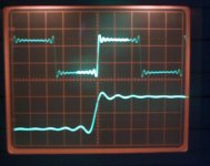
Although nothing to do with the amp design I have attached a shot of a 1 k h z squarewave as reproduced from CD. That kind of puts it into perspective really. Any player will reproduce this the same. Many many years ago Nelson Pass did some tests with slew rates off vinyl which is a system without the absolute bandwidth limitations of CD. I think I am correct in saying the figure was around 2 Volts / microsecond at 100 watts. (Hope I have got that figure correct Nelson )
Personally I am not a great fan of super extended bandwidths for audio amps, much prefering to see a nicely tailored and controlled response with no "nasties" on squarewave testing.
Regards Karl
Gate capacitance is one of the "issues" with FET's it's true (The lateral FET's are quite good in this respect ---600 pf and 900 pf). You have to put it in perspective though. When you talk of "Amperes" of gate current that implies swinging the gate voltage at extremely high slew rates. What would be a sensible value ?
Although nothing to do with the amp design I have attached a shot of a 1 k h z squarewave as reproduced from CD. That kind of puts it into perspective really. Any player will reproduce this the same. Many many years ago Nelson Pass did some tests with slew rates off vinyl which is a system without the absolute bandwidth limitations of CD. I think I am correct in saying the figure was around 2 Volts / microsecond at 100 watts. (Hope I have got that figure correct Nelson
)Personally I am not a great fan of super extended bandwidths for audio amps, much prefering to see a nicely tailored and controlled response with no "nasties" on squarewave testing.
Regards Karl
Attachments
Mooly said:Hello Jerluwoo,
Gate capacitance is one of the "issues" with FET's it's true (The lateral FET's are quite good in this respect ---600 pf and 900 pf). You have to put it in perspective though. When you talk of "Amperes" of gate current that implies swinging the gate voltage at extremely high slew rates. What would be a sensible value ?
Although nothing to do with the amp design I have attached a shot of a 1 k h z squarewave as reproduced from CD. That kind of puts it into perspective really. Any player will reproduce this the same. Many many years ago Nelson Pass did some tests with slew rates off vinyl which is a system without the absolute bandwidth limitations of CD. I think I am correct in saying the figure was around 2 Volts / microsecond at 100 watts. (Hope I have got that figure correct Nelson
Personally I am not a great fan of super extended bandwidths for audio amps, much prefering to see a nicely tailored and controlled response with no "nasties" on squarewave testing.
Regards Karl
In my designs I always filter out frequencies not required.
This helps stop oscilation and RF demodulation !
One of my first Maplin amps picked up the local police radio a treat !
and they can't get close to a 20kHz squarewave.Mooly said:.......I have attached a shot of a 1kHz squarewave as reproduced from CD.
The filters on the front end of the amp, both low pass and high pass, should be adjusted to pass the wanted signal and attenuate the unwanted signal.
As for slew rate, 20 to 30V/uS is sufficient for most listeners.
Hi Andrew,
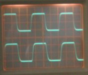
Got the camera out, and took some real screen shots.
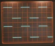
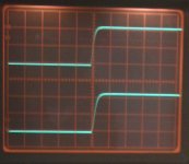
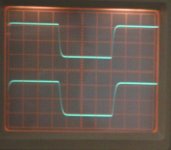
NOTE, The top trace is the input to the power amp but this signal has been through the preamp first ( it is an integrated amp after all ), where the preamp also has a "tailored response". The amp was delivering around 1.6 watts R.M.S. into 5 ohms.
I would suggest that anyone viewing these looks back at post #153 for a 1khz signal from CD which if that is what you use as a source is as good as it gets.
This shows the response at 1 Khz
Got the camera out, and took some real screen shots.
NOTE, The top trace is the input to the power amp but this signal has been through the preamp first ( it is an integrated amp after all ), where the preamp also has a "tailored response". The amp was delivering around 1.6 watts R.M.S. into 5 ohms.
I would suggest that anyone viewing these looks back at post #153 for a 1khz signal from CD which if that is what you use as a source is as good as it gets.
This shows the response at 1 Khz
Attachments
- Home
- Amplifiers
- Solid State
- My MOSFET amplifier designed for music